Search Microcontrollers

Showing posts with label Interrupt. Show all posts

Tuesday, May 19, 2015

Cortex M3 - UART / 2

Interrupts are cool.
No, seriously, if you played with serial communications you know that using an ISR helps a lot because you never know when the other device decides to send a few bytes on the line.
Asynchronous communication in full duplex baby!

So it is good to have an Interrupt Service Routine that gets the data for you from the line while you are busy doing other things.
Typically you are going to have a buffer with two pointers: one knows where to find the first location in the buffer where to write data and the other knows the first location where you did not get data out of the buffer yet.
If the two pointers point to the same lcoation, then there is no data to be extracted from the buffer.

In general this is a convenient way to buy some time and check every now and then if we received some data.
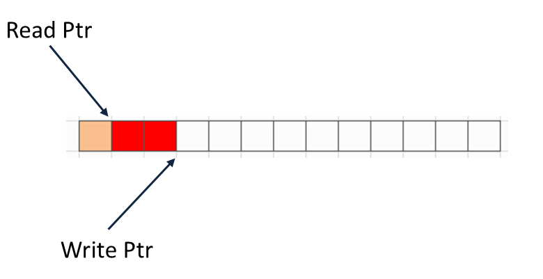

In the image above you can see an example where 3 bytes were received, so the write pointer points to the 4th location and 1 byte was read from the buffer, so the Read Ptr points to the 2nd location.
The two pointers have different values, so there is still data to be read in the buffer.
Obviously while you read and write you increment the relevant pointer, resetting it to zero when it reaches the end of the buffer.

This is one way to manage asynchronous communications, of course you could add some logic in your Interrupt handler routine to make your application react immediately i.e. when a specific character is received.
It is in genreral good practice, tho, to have as little logic as possible in the ISR routines, they should complete in the shortest amount of time possible.

Now, the funny thing is that the buffer we described is also called a FIFO (First In-First Out) buffer... which is already supported via hardware in the Cortex M3.

That's right, if you needed just a few bytes in your buffer, no need to set up an ISR, you could simply enable the internal FIFO and you can still do it even if you decide to use interrupts.

void SER_fifo(int uart,uint32_t enable,uint32_t dma,uint32_t trigger)
{
LPC_UART_TypeDef *pUart;
pUart = __get_uart_base(uart);
pUart->FCR |= (enable&0x1)|((dma&1)<<3)|((trigger&0x3)<<6);
}

The Fifo Control Register (FCR) can be used to enable the Fifo, define how many bytes should be received by it before triggering an IRQ and if it should use a dma channel to automatically copy the data to a specific memory location.
Neat eh?

@NXP

You can also reset the fifos (both the output fifo and the input fifo)... wait.. output fifo?
Yes, serial communication might be a bit slow for MCUs and imagine you need to send a few bytes out: the output fifo will be happy to store some of those bytes for you so you can go have fun doing other interesting tasks while it handles the communication.
You can do the same thing with an ISR routine or even use both at the same time.
Notice that you can activate both (RX and TX) fifos or none of them, but you cannot activate just RX and not TX or the other way round.

Now, let's see the interrupts.


The UARTxIER are the Interrupt Enable Registers for the various UARTS.
There are two interrupts we want to consider there :
- The one generated when a new byte is received (or when the number of bytes in the fifo reaches the trigger threshold, if enabled) and this is the RBR one.
- The other, generated when the line is ready to send out some new data, meet the THRE (Transmit Hold Register Empty) interrupt.
The third one is triggered when the status of the receive line changes.

#define IER_RBR  0x01
#define IER_THRE 0x02
#define IER_RXLS 0x04
pUart->IER = IER_RBR | IER_THRE | IER_RXLS;  

That line enables the uart interrupts... almost.
Actually we also need to enable the Uartx IRQ in the Nested Vector Interrupt Controller (NVIC)  which has a cool name because it does cool stuff.

switch (uart)
{
  case 0: NVIC_EnableIRQ(UART0_IRQn); break;
  case 2: NVIC_EnableIRQ(UART2_IRQn); break;
  case 3: NVIC_EnableIRQ(UART3_IRQn); break;
}

Now interrupts will be fired upon events and we should really do something with them.
To capture them we just need to define a function (one per each uart we use) with a specific name, I am using uart2 so :

void UART2_IRQHandler(void) __irq
{
   ...
}

Now we need to fill it with some good code, because I never had luck in succesfully compiling a statement like "...", so I guess it's not going to work for you either.

First thing, let's just say we want to have an input buffer which will be filled by the IRQHandler procedure.

#define UART_RX_BUFSIZE 32
uint8_t UART_RxBuf[UART_RX_BUFSIZE];
uint8_t bufWptr =0;
uint8_t bufRptr = 0;

Then we need to consider that the IRQHandler will be called for every kind of uart (uart2 in my case) related interrupt.
By "every" we actually mean as many as you can count with two fingers (or two bits), in other words : four.

This is the Interrupt Identification Register (IIR) which can be used to get the IntID, a 2 bit number that identifies which interrupt we are dealing with.


void UART2_IRQHandler(void) __irq
{
uint8_t intId;
intId = ((LPC_UART2->IIR)>>1)& 0x7;

switch (intId)
{
  case INTID_RXLS : break;// whatever
  case INTID_RDA  : 
while((LPC_UART2->LSR) & 0x1) 
                {
        UART_RxBuf[bufWptr++] = LPC_UART2->RBR;
        if (bufWptr >= UART_RX_BUFSIZE)
         bufWptr = 0;
}
break;
  case INTID_CTI  : break; // whatever
  case INTID_THRE : break; // whatever
}
}

This is a simple implementation that should provide RX interrupt handling, notice it does not check if our software buffer is overran.

Let's just add a couple of functions to get the data out of the buffer and check if we should do it.

int SER_hasBufData()
{
 return (bufWptr!=bufRptr);
}

uint8_t SER_getBufData()
{
 if (bufRptr>=UART_RX_BUFSIZE) bufRptr=0;
 return UART_RxBuf[bufRptr++];
}

And finally we can update the test program

int main(void)
{
  SystemInit();
  setpll0(25,2,3);
  SystemCoreClockUpdate();
  SER_init(2,115200);
  SER_fifo(2,1,0,0);
  while (1) 
  {
   delay(10000000);
   SER_putString (2, ".");
   while (SER_hasBufData())
   {
SER_putString (2, "Received : ");
SER_putChar(2,SER_getBufData());
SER_putString (2, "\r\n");
   }  
  }
  return 0;
}

As usual, you can get my full code here.

Friday, April 11, 2014

Stellaris Launchpad - Stepper Motors

I just noticed I had a post in my drafts, almost ready to be published, it was lying there since some time...

Stepper motors are fun, right?
You can easily find cheap stepper motors that can be driven by MCUs, they need a driver circuit as MCUs cannot provide enough current via their GPIO ports, but these drivers are normally just a set of simple transistors.

I experimented with a  small 28BYJ 5V Stepper Motor which contains a gearbox that allows it to deliver a decent torque and precision (sacrificing the rotation speed).


There are libraries for Arduino and maybe even for ARM Cortex MCUs, not sure about that, but, as usual, I wanted to get my fingers dirty and experiment a bit.

A typical driver for this motor is the ULN2003 driver, which is just a darlington array that delivers just enough juice for the 28BYJ (500mA).
Those darlingtons can also be activated via a 3.3V GPIO, base resistors and protection diodes are already included in the package... pretty easy, no?


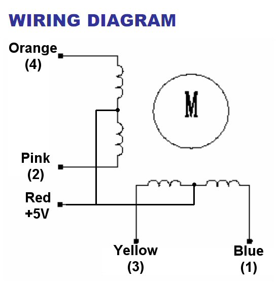
For the 28BYJ only 4 transistors are used, common is connected to +5V.
You need an external power supply to provide this 5V as you need 500mA, remember to connect the ground of the additional PSU to the launchpad ground.

So, the circuit itself is quite simple, I used a simple board for the ULN2003, which I bought together with the motor (it is quite common) so I did not have to mess around with soldering etc.


The motor has 4 phases that must be activated in the correct sequence of 8 steps to obtain a clockwise rotation or in the opposite sequence should you want to achieve a counter-clockwise one.

Easiest thing to do is to create an array with the 4 bits and the 8 steps cycle.

unsigned char steps[8] ={0b0001,0b0011,0b0010,0b0110,0b0100,0b1100,0b1000,0b1001};

each one of those bits should be addressed to a GPIO pin, I used pins  D.0, D.1, D.2 and D.3 which can be found on the J3 connector of the launchpad. 

So, the first step 0b0001 would set D.0 high and the three other ones low.

I then decided to use a timer with an associated interrupt to cycle the steps.
Setting the timer value is key because we are dealing with a  mechanical thing here, it has inertia and therefore can reach a maximum rotation speed that cannot be exceed (it would stall).
Setting the correct speed depends also on the load you have attached to the motor.

Of course providing a nice acceleration ramp lets you achieve higher rotation speeds, however I am not sure it is a good idea in a real application because if the motor misses a few steps due to exceptional load, then you might be driving it at a speed it cannot achieve starting from zero, and would remain stalled. 
You can try that, simply block the rotation when it runs faster than it can from still and see what happens.


Ok, back to my test program.
I wanted to use the two user switches on the launchpad to make it rotate 180deg in each direction.

I then created a variable int cntSteps = 0;  which represents the number of steps to be executed, if it has  a negative value then I will traverse the steps array backwards.
This is done in the nextStep() procedure.
I also need a int step variable to identify the position within the array of the current step.

void nextStep()
{
if (cntSteps>0)
{
GPIOPinWrite(GPIO_PORTF_BASE, GPIO_PIN_1|GPIO_PIN_2|GPIO_PIN_3,GPIO_PIN_1); //red
if (step<7) step++; else step=0;
    cntSteps--;
}
else
{
GPIOPinWrite(GPIO_PORTF_BASE, GPIO_PIN_1|GPIO_PIN_2|GPIO_PIN_3,GPIO_PIN_2); //blue
if (step>0) step--; else step=8;
cntSteps++;
}
GPIOPinWrite(GPIO_PORTD_BASE, 0x0f, steps[step]&0x0f);
}

Depending on the sign of the cntSteps variable I cycle through the array and finally output the 4 bit value (masked, just in case) to the GPIO port D.
I also added a blue led on if turning in one direction and red if turning in the opposite one.
When the motor is still, the LED is green indicating the system is ready to receive another command. 

This is visible in the Time Interrupt Handler (you can find more info on interrupts here)

// timer interrupt handler
void timerIntHandler(void)
{
   TimerIntClear(TIMER0_BASE, TIMER_TIMA_TIMEOUT);
    if (cntSteps!=0)
    nextStep();
    else GPIOPinWrite(GPIO_PORTF_BASE, GPIO_PIN_1|GPIO_PIN_2|GPIO_PIN_3,GPIO_PIN_3);
}

If we need to move (cntSteps!=0) then the next  Step is executed else, the LED is turned green.

Interrupt handlers must be registered, that's  done in the setup_ccs.c file of the project, in the #pragma DATA_SECTION(g_pfnVectors, ".intvecs") structure.


In my case, I used two interrupt handlers, one for the two switches and one for the timer0_A, I located the position of the GPIO PORT F and TIMER 0 A and then replaced the defaultHandler with the procedures I created in my main.c file.

Since these procedures are defined in main.c, you need to declare the external before the int vec structure we just discussed, still in startup_ccs.c :

//------------- custom int handlers
extern void timerIntHandler(void);
extern void switchIntHandler(void);

Ok, now let's see how the user switch interrupt handler works.

// switch interrupt handler
void switchIntHandler(void)
{
GPIOPinIntClear(GPIO_PORTF_BASE,GPIO_PIN_0
                                       |GPIO_PIN_4);
if (cntSteps==0)
{
if (GPIOPinRead(GPIO_PORTF_BASE,
                          GPIO_PIN_0|GPIO_PIN_4)
                        &GPIO_PIN_4 > 0)
                 addAngle((double)180.0f);
else addAngle((double)-180.0f);
}

}

As you can see I created a single handler for both switches, this is possible because they are both on the same GPIO port (F).
Using the interrupt on F.0 is not trivial and requires some funny coding, but I will dig into that later.

The addAngle procedure is quite simple, it converts an angle into a number of steps knowing that there are a total of 4076 steps in 360 degrees (not really sure of that value, I found it online, you may want to double check eventually) taking into account also the reduction gears.

// -- adds a specific number of steps depending on the needed angle
void addAngle(double deg) // 4076 steps
{
double newAngle =deg*4076/360;
  cntSteps += newAngle;
}

Finally , we are just missing the setup part.

// configure mcu clock speed
void setClock()
{
 //25 MHZ
 SysCtlClockSet(  
         SYSCTL_SYSDIV_8 |SYSCTL_USE_PLL | 
         SYSCTL_XTAL_16MHZ  | SYSCTL_OSC_MAIN);
}

// stepper timer setup
void setTimer(int stepsPerSec)
{
    SysCtlPeripheralEnable(SYSCTL_PERIPH_TIMER0);
    TimerConfigure(TIMER0_BASE, TIMER_CFG_PERIODIC);
    TimerLoadSet(TIMER0_BASE, TIMER_A, 
            SysCtlClockGet()/ stepsPerSec);
    IntEnable(INT_TIMER0A);
    TimerIntEnable(TIMER0_BASE, TIMER_TIMA_TIMEOUT);
    TimerEnable(TIMER0_BASE, TIMER_A);
}

These two procedures set up the MCU clock to 25MHz and prepare the timer to fire an interrupt stepsPerSec times each second.
We are just missing the gpio setup part and here I had to do something  a bit unconventional.
If you check the launchpad schematics, you will notice that the user switch 2 has an additional connection called WAKE


Practically by default this switch generates an NMI (Non Maskable Interrupt) used to wake the CPU from sleep modes.
Unfortunately this functionality interferes with the Interrupt handler for SW2 (D.0), unless you " massage"  it properly.

  //workaround for pin_0 to nmi
    HWREG(GPIO_PORTF_BASE + GPIO_O_LOCK) =   GPIO_LOCK_KEY_DD;
    HWREG(GPIO_PORTF_BASE + GPIO_O_CR) |= 0x01;
    HWREG(GPIO_PORTF_BASE + GPIO_O_LOCK) = 0;
I am note really sure what it does, I just found it online and it works, you add that to your GPIO configuration and magically sw2 can be serviced with an interrupt handler.

The complete GPIO setup is as follows :

// GPIO & Interrupt configuration
void setGPIO()
{
SysCtlPeripheralEnable(SYSCTL_PERIPH_GPIOF); 
  // to read switches
SysCtlPeripheralEnable(SYSCTL_PERIPH_GPIOD); 
  // used to output stepper signals

GPIOPadConfigSet(GPIO_PORTD_BASE, // identifies the GPIO PORT
0x0f,                 // identifies the pin within the GPIO Port
GPIO_STRENGTH_8MA_SC, // sets the strength to 8mA with Slew Rate control
GPIO_PIN_TYPE_STD);   // sets the pad control type to push-pull
GPIOPinTypeGPIOOutput(GPIO_PORTD_BASE, GPIO_PIN_0|GPIO_PIN_1|GPIO_PIN_2|GPIO_PIN_3);

    // setup LEDs
GPIOPinTypeGPIOOutput(GPIO_PORTF_BASE, GPIO_PIN_1|GPIO_PIN_2|GPIO_PIN_3);
GPIOPadConfigSet(GPIO_PORTF_BASE,
GPIO_PIN_1|GPIO_PIN_2|GPIO_PIN_3,
GPIO_STRENGTH_8MA_SC,
GPIO_PIN_TYPE_STD);
    //turn LEDs off
GPIOPinWrite(GPIO_PORTF_BASE, GPIO_PIN_1|GPIO_PIN_2|GPIO_PIN_3,0);

    IntMasterEnable(); // enable processor interrupts

    //workaround for pin_0 to nmi
    HWREG(GPIO_PORTF_BASE + GPIO_O_LOCK) = GPIO_LOCK_KEY_DD;
    HWREG(GPIO_PORTF_BASE + GPIO_O_CR) |= 0x01;
    HWREG(GPIO_PORTF_BASE + GPIO_O_LOCK) = 0;

    // set the two switches as inputs
GPIOPinTypeGPIOInput(GPIO_PORTF_BASE,GPIO_PIN_0|GPIO_PIN_4);
GPIOPadConfigSet(GPIO_PORTF_BASE, GPIO_PIN_0|GPIO_PIN_4,
         GPIO_STRENGTH_4MA,
         GPIO_PIN_TYPE_STD_WPU); // configure input pads
// interrupt set to falling edge since the switches are normally "high"
// they indeed know how to have fun, lol :P
GPIOIntTypeSet(GPIO_PORTF_BASE,GPIO_PIN_0|GPIO_PIN_4, GPIO_FALLING_EDGE);
GPIOPortIntRegister(GPIO_PORTF_BASE,switchIntHandler);
GPIOPinIntEnable(GPIO_PORTF_BASE,GPIO_PIN_4|GPIO_PIN_0);
}

If you check again the switch schematics, you will notice that when they are pressed, they are connected to ground, so it is appropriate to use a falling_edge interrupt to detect when they are pressed.
In my case this is important because I am using a single ISR for both switches and I need to check which one is pressed, if I used a raising_edge interrupt, the ISR would have been activated when the button was released and I could not tell which one of the two was released by reading the GPIO port.

finally, the main cycle is trivial :

int main(void) {
 setClock();
 setGPIO();
 cntSteps = 0;
 setTimer(800);//steps per second
 while (1) {}// do nothing, interrupts will handle that
} // main
You can find the full code here

Have fun with stepper motors, interrupts and switches!
Should you be looking for this stepper motors, chances are you can find it cheap here :

Tuesday, February 18, 2014

Stellaris Launchpad - Interrupts 1

The Cortex M4F has a powerful interrupt handling mechanism.
Since these kind of devices are normally used in applications where they control events happening around them, they need to have a flexible and efficient interrupt handling mechanism.

If you ever coded ISR (Interrupt Service Routines) for pretty much any platform, you probably know that is generally a bad idea to have two interrupts serviced at the same time.
When an interrupt is being serviced, a second interrupt is generally queued and waits for the first ISR to be completed.
While in many applications this could be ok -i.e. you click with your mouse and press a key on your keyboard almost simultaneously, but it is usually ok for the keyboard event to wait until the mouse event is handled or vice-versa-
When you are dealing with external sensors that might require a very quick response, this behavior may not be desirable or even acceptable.
What would be cool is to be able to set priorities to those interrupts and if the keyboard is more important of the mouse then we expect the mouse ISR routine to be interrupted by the keyboard one and resume right after the latter is completed.

The cortex M4F allows just that using a Nested Vector Interrupt Controller (NVIC) that handles via hardware all the needed complexity (Pushing a popping the machine states as needed and optimizing such processes for Interrupt concurrency).

These concepts are well explained in the great video by TI


To be honest I am not adding much with this post as everything is well explained in the video itself, however, for my (and eventually yours) future reference, I find it easier to write a summary of the concepts.

Now that you know how cool the interrupt handling is in the M4F, let's see how to use it in a basic setup.

By default all interrupt vector are redirected to a default vector function called IntDefaultHandler.
If you enable a timer interrupt, a uart interrupt etc, the interrupt vector function found in the MCU vector table (by default it starts at addr 0x0, leave it there unless you have a good reason not too) is called.

The Stellaris has 65 interrupts, each one has a service function address stored in the int vector table.
This means that if you want to use your interrupt service routine, you need to store its address in the before mentioned table.

Configuring your startup_ccs.c file

To achieve this you need to properly alter the file startup_ccs.c (you have a copy of it in each CCS project) file in two points :

1) Search for this data structure :

 #pragma DATA_SECTION(g_pfnVectors, ".intvecs")
void (* const g_pfnVectors[])(void) =

You will find an array of function pointers, on the right side comments are added to indicate which ISR each value represents.
Carefully browse those comments and locate the element related to the interrupt you need to handle.
Most likely the associated value will be IntDefaultHandler, if it is not either you already mdified the file or you are trying to manage something you probably should not (a reserved or "core" interrupt).
Replace IntDefaultHandler with the name of your ISR function (i.e. MyCoolISRFunction ) .


2) Now you updated the int vector table  to consider your ISR, however in the startup_ccs.c file such function is normally not defined (you defined it in your main.c or whatever other source file you are using).
To fix that, scroll on top of startup_ccs.c and locate a section that contains external declarations, it should be around line 20 or so.
There add your ISR as

extern void MyCoolISRFunction;    

where MyCoolISRFunction is the same name you used to define the ISR in main.c and you copied into the int vector table structure.

Steps needed to service a peripheral using an ISR 

1) Enable your peripheral XXXX with

 SysCtlPeripheralEnable(XXXX);

2) configure your peripheral as needed by setting gpio pind directions, timer, uart, spi... parameters

3) Enable the interrupt associated to your peripheral
IntEnable(XXXX);

4) Enable your peripheral to generate interrupts
i.e. TimerIntEnable(TIMER0_BASE,TIMER_TIMA_TIMEOUT);

5) Generally enable interrupts on the M4F
IntMasterEnable();

6) Fire up your peripheral if needed
i.e. TimerEnable(TIMER0_BASE,TIMER_A);

7) define your ISR function

void MyCoolISRFunction(void)
{
 // clear the peripheral interrupt i.e. :
 TimerIntClear(TIMER0_BASE,TIMER_TIMA_TIMEOUT);
/*
 do whatever you need to do
*/
}

Note that all steps from 1 to 7 happened in your main.c (or other source module you may have added) file.

8) Finally you need to update your startup_ccs.c file as explained in the "configure your startup_ccs.c file" section