Stepper motors are fun, right?
You can easily find cheap stepper motors that can be driven by MCUs, they need a driver circuit as MCUs cannot provide enough current via their GPIO ports, but these drivers are normally just a set of simple transistors.
I experimented with a small 28BYJ 5V Stepper Motor which contains a gearbox that allows it to deliver a decent torque and precision (sacrificing the rotation speed).

There are libraries for Arduino and maybe even for ARM Cortex MCUs, not sure about that, but, as usual, I wanted to get my fingers dirty and experiment a bit.
A typical driver for this motor is the ULN2003 driver, which is just a darlington array that delivers just enough juice for the 28BYJ (500mA).
Those darlingtons can also be activated via a 3.3V GPIO, base resistors and protection diodes are already included in the package... pretty easy, no?

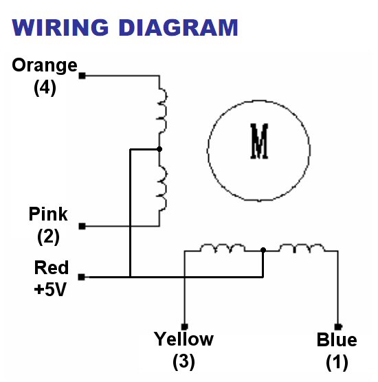
For the 28BYJ only 4 transistors are used, common is connected to +5V.
You need an external power supply to provide this 5V as you need 500mA, remember to connect the ground of the additional PSU to the launchpad ground.
So, the circuit itself is quite simple, I used a simple board for the ULN2003, which I bought together with the motor (it is quite common) so I did not have to mess around with soldering etc.
The motor has 4 phases that must be activated in the correct sequence of 8 steps to obtain a clockwise rotation or in the opposite sequence should you want to achieve a counter-clockwise one.
Easiest thing to do is to create an array with the 4 bits and the 8 steps cycle.
unsigned char steps[8] ={0b0001,0b0011,0b0010,0b0110,0b0100,0b1100,0b1000,0b1001};
each one of those bits should be addressed to a GPIO pin, I used pins D.0, D.1, D.2 and D.3 which can be found on the J3 connector of the launchpad.
So, the first step 0b0001 would set D.0 high and the three other ones low.
I then decided to use a timer with an associated interrupt to cycle the steps.
Setting the timer value is key because we are dealing with a mechanical thing here, it has inertia and therefore can reach a maximum rotation speed that cannot be exceed (it would stall).
Setting the correct speed depends also on the load you have attached to the motor.
Of course providing a nice acceleration ramp lets you achieve higher rotation speeds, however I am not sure it is a good idea in a real application because if the motor misses a few steps due to exceptional load, then you might be driving it at a speed it cannot achieve starting from zero, and would remain stalled.
You can try that, simply block the rotation when it runs faster than it can from still and see what happens.

Ok, back to my test program.
I wanted to use the two user switches on the launchpad to make it rotate 180deg in each direction.
I then created a variable int cntSteps = 0; which represents the number of steps to be executed, if it has a negative value then I will traverse the steps array backwards.
This is done in the nextStep() procedure.
I also need a int step variable to identify the position within the array of the current step.
void nextStep()
{
if (cntSteps>0)
{
GPIOPinWrite(GPIO_PORTF_BASE, GPIO_PIN_1|GPIO_PIN_2|GPIO_PIN_3,GPIO_PIN_1); //red
if (step<7) step++; else step=0;
cntSteps--;
}
else
{
GPIOPinWrite(GPIO_PORTF_BASE, GPIO_PIN_1|GPIO_PIN_2|GPIO_PIN_3,GPIO_PIN_2); //blue
if (step>0) step--; else step=8;
cntSteps++;
}
GPIOPinWrite(GPIO_PORTD_BASE, 0x0f, steps[step]&0x0f);
}
Depending on the sign of the cntSteps variable I cycle through the array and finally output the 4 bit value (masked, just in case) to the GPIO port D.
I also added a blue led on if turning in one direction and red if turning in the opposite one.
When the motor is still, the LED is green indicating the system is ready to receive another command.
This is visible in the Time Interrupt Handler (you can find more info on interrupts here)
// timer interrupt handler
void timerIntHandler(void)
{
TimerIntClear(TIMER0_BASE, TIMER_TIMA_TIMEOUT);
if (cntSteps!=0)
nextStep();
else GPIOPinWrite(GPIO_PORTF_BASE, GPIO_PIN_1|GPIO_PIN_2|GPIO_PIN_3,GPIO_PIN_3);
}
If we need to move (cntSteps!=0) then the next Step is executed else, the LED is turned green.
Interrupt handlers must be registered, that's done in the setup_ccs.c file of the project, in the #pragma DATA_SECTION(g_pfnVectors, ".intvecs") structure.

In my case, I used two interrupt handlers, one for the two switches and one for the timer0_A, I located the position of the GPIO PORT F and TIMER 0 A and then replaced the defaultHandler with the procedures I created in my main.c file.
Since these procedures are defined in main.c, you need to declare the external before the int vec structure we just discussed, still in startup_ccs.c :
//------------- custom int handlers
extern void timerIntHandler(void);
extern void switchIntHandler(void);
Ok, now let's see how the user switch interrupt handler works.
// switch interrupt handler
void switchIntHandler(void)
{
GPIOPinIntClear(GPIO_PORTF_BASE,GPIO_PIN_0
|GPIO_PIN_4);
if (cntSteps==0)
{
if (GPIOPinRead(GPIO_PORTF_BASE,
GPIO_PIN_0|GPIO_PIN_4)
&GPIO_PIN_4 > 0)
addAngle((double)180.0f);
else addAngle((double)-180.0f);
}
}
As you can see I created a single handler for both switches, this is possible because they are both on the same GPIO port (F).
Using the interrupt on F.0 is not trivial and requires some funny coding, but I will dig into that later.
The addAngle procedure is quite simple, it converts an angle into a number of steps knowing that there are a total of 4076 steps in 360 degrees (not really sure of that value, I found it online, you may want to double check eventually) taking into account also the reduction gears.
// -- adds a specific number of steps depending on the needed angle
void addAngle(double deg) // 4076 steps
{
double newAngle =deg*4076/360;
cntSteps += newAngle;
}
Finally , we are just missing the setup part.
// configure mcu clock speed
void setClock()
{
//25 MHZ
SysCtlClockSet(
SYSCTL_SYSDIV_8 |SYSCTL_USE_PLL |
SYSCTL_XTAL_16MHZ | SYSCTL_OSC_MAIN);
}
// stepper timer setup
void setTimer(int stepsPerSec)
{
SysCtlPeripheralEnable(SYSCTL_PERIPH_TIMER0);
TimerConfigure(TIMER0_BASE, TIMER_CFG_PERIODIC);
TimerLoadSet(TIMER0_BASE, TIMER_A,
SysCtlClockGet()/ stepsPerSec);
IntEnable(INT_TIMER0A);
TimerIntEnable(TIMER0_BASE, TIMER_TIMA_TIMEOUT);
TimerEnable(TIMER0_BASE, TIMER_A);
}
These two procedures set up the MCU clock to 25MHz and prepare the timer to fire an interrupt stepsPerSec times each second.
We are just missing the gpio setup part and here I had to do something a bit unconventional.
If you check the launchpad schematics, you will notice that the user switch 2 has an additional connection called WAKE

Practically by default this switch generates an NMI (Non Maskable Interrupt) used to wake the CPU from sleep modes.
Unfortunately this functionality interferes with the Interrupt handler for SW2 (D.0), unless you " massage" it properly.
//workaround for pin_0 to nmi
HWREG(GPIO_PORTF_BASE + GPIO_O_LOCK) = GPIO_LOCK_KEY_DD;
HWREG(GPIO_PORTF_BASE + GPIO_O_CR) |= 0x01;
HWREG(GPIO_PORTF_BASE + GPIO_O_LOCK) = 0;
I am note really sure what it does, I just found it online and it works, you add that to your GPIO configuration and magically sw2 can be serviced with an interrupt handler.
The complete GPIO setup is as follows :
// GPIO & Interrupt configuration
void setGPIO()
{
SysCtlPeripheralEnable(SYSCTL_PERIPH_GPIOF);
// to read switches
SysCtlPeripheralEnable(SYSCTL_PERIPH_GPIOD);
// used to output stepper signals
GPIOPadConfigSet(GPIO_PORTD_BASE, // identifies the GPIO PORT
0x0f, // identifies the pin within the GPIO Port
GPIO_STRENGTH_8MA_SC, // sets the strength to 8mA with Slew Rate control
GPIO_PIN_TYPE_STD); // sets the pad control type to push-pull
GPIOPinTypeGPIOOutput(GPIO_PORTD_BASE, GPIO_PIN_0|GPIO_PIN_1|GPIO_PIN_2|GPIO_PIN_3);
// setup LEDs
GPIOPinTypeGPIOOutput(GPIO_PORTF_BASE, GPIO_PIN_1|GPIO_PIN_2|GPIO_PIN_3);
GPIOPadConfigSet(GPIO_PORTF_BASE,
GPIO_PIN_1|GPIO_PIN_2|GPIO_PIN_3,
GPIO_STRENGTH_8MA_SC,
GPIO_PIN_TYPE_STD);
//turn LEDs off
GPIOPinWrite(GPIO_PORTF_BASE, GPIO_PIN_1|GPIO_PIN_2|GPIO_PIN_3,0);
IntMasterEnable(); // enable processor interrupts
//workaround for pin_0 to nmi
HWREG(GPIO_PORTF_BASE + GPIO_O_LOCK) = GPIO_LOCK_KEY_DD;
HWREG(GPIO_PORTF_BASE + GPIO_O_CR) |= 0x01;
HWREG(GPIO_PORTF_BASE + GPIO_O_LOCK) = 0;
// set the two switches as inputs
GPIOPinTypeGPIOInput(GPIO_PORTF_BASE,GPIO_PIN_0|GPIO_PIN_4);
GPIOPadConfigSet(GPIO_PORTF_BASE, GPIO_PIN_0|GPIO_PIN_4,
GPIO_STRENGTH_4MA,
GPIO_PIN_TYPE_STD_WPU); // configure input pads
// interrupt set to falling edge since the switches are normally "high"
// they indeed know how to have fun, lol :P
GPIOIntTypeSet(GPIO_PORTF_BASE,GPIO_PIN_0|GPIO_PIN_4, GPIO_FALLING_EDGE);
GPIOPortIntRegister(GPIO_PORTF_BASE,switchIntHandler);
GPIOPinIntEnable(GPIO_PORTF_BASE,GPIO_PIN_4|GPIO_PIN_0);
}
If you check again the switch schematics, you will notice that when they are pressed, they are connected to ground, so it is appropriate to use a falling_edge interrupt to detect when they are pressed.
In my case this is important because I am using a single ISR for both switches and I need to check which one is pressed, if I used a raising_edge interrupt, the ISR would have been activated when the button was released and I could not tell which one of the two was released by reading the GPIO port.
finally, the main cycle is trivial :
int main(void) {
setClock();
setGPIO();
cntSteps = 0;
setTimer(800);//steps per second
while (1) {}// do nothing, interrupts will handle that
} // main
You can find the full code here
Have fun with stepper motors, interrupts and switches!
Should you be looking for this stepper motors, chances are you can find it cheap here :
5 comments:
Wonderful post. Do you know the maximum current that LaunchPad MSP-EXP430F5529LP can provide to drive the stepper? I am using the same motor and ULN2003 driver as you are. I connected it to 5V on LP. It worked. I later connected it to 3.3V on LP. It still worked. LaunchPad is powered from USB. So, do I really need a separate power supply? Thx.
Hello Arvind, thanks for your comment.
Theoretically you might get away with just using the usb... but you are a bit at limit there.
Going down to 3.3V or failing to provide enough mAmps (500mA is what the driver can deliver... and is also the USB 2.0 limit) might make your stepper to lose steps, particularly if moving fast or if you apply some reaction torque.
You can easily check that by playing with the timer interval.
So, to experiment a bit on your desk, with no load, you might get away without a separate power supply, but for any real application I strongly suggest you use a separate line.
Sorry I just realized what you may have wanted to ask...
Do you mean drive the motor directly from the GPIO without using a driver circuit?
In that case no, GPIO can be configured at 8mA max if I remember correctly, plus you would need a bypassing diode on each phase for the inductive load.
DO NOT connect directly the phases to the GPIO as if it gets enough current to move you would probably burn your GPIOs.
Thanks. Both your replies are useful. I am in fact using a driver: http://www.lctech-inc.com/Hardware/Detail.aspx?id=af45ebe8-fc25-448c-8f02-f6848399d4ff
With the driver, can I safely say that the current is coming from the driver without taxing the LaunchPad or burning out its GPIO pins?
Right now I am using this driver to conduct a hands-on workshop without using any load. But in a real application, as you say, I will use a separate power supply.
Correct, you are using the same driver I used in my experiment.
The driver is designed so that the GPIO is only used to "open the channels" that are powered separately and this requires a minimal load, well within the limits of the GPIO.
The driver itself should normally be powered with a separate line, providing 500mA, but with that small motor and no load it can work with the Vcc pulled from the launchpad.
Post a Comment