Search Microcontrollers

Showing posts with label uart. Show all posts

Tuesday, May 19, 2015

Cortex M3 - UART / 2

Interrupts are cool.
No, seriously, if you played with serial communications you know that using an ISR helps a lot because you never know when the other device decides to send a few bytes on the line.
Asynchronous communication in full duplex baby!

So it is good to have an Interrupt Service Routine that gets the data for you from the line while you are busy doing other things.
Typically you are going to have a buffer with two pointers: one knows where to find the first location in the buffer where to write data and the other knows the first location where you did not get data out of the buffer yet.
If the two pointers point to the same lcoation, then there is no data to be extracted from the buffer.

In general this is a convenient way to buy some time and check every now and then if we received some data.
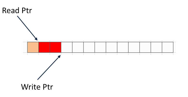

In the image above you can see an example where 3 bytes were received, so the write pointer points to the 4th location and 1 byte was read from the buffer, so the Read Ptr points to the 2nd location.
The two pointers have different values, so there is still data to be read in the buffer.
Obviously while you read and write you increment the relevant pointer, resetting it to zero when it reaches the end of the buffer.

This is one way to manage asynchronous communications, of course you could add some logic in your Interrupt handler routine to make your application react immediately i.e. when a specific character is received.
It is in genreral good practice, tho, to have as little logic as possible in the ISR routines, they should complete in the shortest amount of time possible.

Now, the funny thing is that the buffer we described is also called a FIFO (First In-First Out) buffer... which is already supported via hardware in the Cortex M3.

That's right, if you needed just a few bytes in your buffer, no need to set up an ISR, you could simply enable the internal FIFO and you can still do it even if you decide to use interrupts.

void SER_fifo(int uart,uint32_t enable,uint32_t dma,uint32_t trigger)
{
LPC_UART_TypeDef *pUart;
pUart = __get_uart_base(uart);
pUart->FCR |= (enable&0x1)|((dma&1)<<3)|((trigger&0x3)<<6);
}

The Fifo Control Register (FCR) can be used to enable the Fifo, define how many bytes should be received by it before triggering an IRQ and if it should use a dma channel to automatically copy the data to a specific memory location.
Neat eh?

@NXP

You can also reset the fifos (both the output fifo and the input fifo)... wait.. output fifo?
Yes, serial communication might be a bit slow for MCUs and imagine you need to send a few bytes out: the output fifo will be happy to store some of those bytes for you so you can go have fun doing other interesting tasks while it handles the communication.
You can do the same thing with an ISR routine or even use both at the same time.
Notice that you can activate both (RX and TX) fifos or none of them, but you cannot activate just RX and not TX or the other way round.

Now, let's see the interrupts.


The UARTxIER are the Interrupt Enable Registers for the various UARTS.
There are two interrupts we want to consider there :
- The one generated when a new byte is received (or when the number of bytes in the fifo reaches the trigger threshold, if enabled) and this is the RBR one.
- The other, generated when the line is ready to send out some new data, meet the THRE (Transmit Hold Register Empty) interrupt.
The third one is triggered when the status of the receive line changes.

#define IER_RBR  0x01
#define IER_THRE 0x02
#define IER_RXLS 0x04
pUart->IER = IER_RBR | IER_THRE | IER_RXLS;  

That line enables the uart interrupts... almost.
Actually we also need to enable the Uartx IRQ in the Nested Vector Interrupt Controller (NVIC)  which has a cool name because it does cool stuff.

switch (uart)
{
  case 0: NVIC_EnableIRQ(UART0_IRQn); break;
  case 2: NVIC_EnableIRQ(UART2_IRQn); break;
  case 3: NVIC_EnableIRQ(UART3_IRQn); break;
}

Now interrupts will be fired upon events and we should really do something with them.
To capture them we just need to define a function (one per each uart we use) with a specific name, I am using uart2 so :

void UART2_IRQHandler(void) __irq
{
   ...
}

Now we need to fill it with some good code, because I never had luck in succesfully compiling a statement like "...", so I guess it's not going to work for you either.

First thing, let's just say we want to have an input buffer which will be filled by the IRQHandler procedure.

#define UART_RX_BUFSIZE 32
uint8_t UART_RxBuf[UART_RX_BUFSIZE];
uint8_t bufWptr =0;
uint8_t bufRptr = 0;

Then we need to consider that the IRQHandler will be called for every kind of uart (uart2 in my case) related interrupt.
By "every" we actually mean as many as you can count with two fingers (or two bits), in other words : four.

This is the Interrupt Identification Register (IIR) which can be used to get the IntID, a 2 bit number that identifies which interrupt we are dealing with.


void UART2_IRQHandler(void) __irq
{
uint8_t intId;
intId = ((LPC_UART2->IIR)>>1)& 0x7;

switch (intId)
{
  case INTID_RXLS : break;// whatever
  case INTID_RDA  : 
while((LPC_UART2->LSR) & 0x1) 
                {
        UART_RxBuf[bufWptr++] = LPC_UART2->RBR;
        if (bufWptr >= UART_RX_BUFSIZE)
         bufWptr = 0;
}
break;
  case INTID_CTI  : break; // whatever
  case INTID_THRE : break; // whatever
}
}

This is a simple implementation that should provide RX interrupt handling, notice it does not check if our software buffer is overran.

Let's just add a couple of functions to get the data out of the buffer and check if we should do it.

int SER_hasBufData()
{
 return (bufWptr!=bufRptr);
}

uint8_t SER_getBufData()
{
 if (bufRptr>=UART_RX_BUFSIZE) bufRptr=0;
 return UART_RxBuf[bufRptr++];
}

And finally we can update the test program

int main(void)
{
  SystemInit();
  setpll0(25,2,3);
  SystemCoreClockUpdate();
  SER_init(2,115200);
  SER_fifo(2,1,0,0);
  while (1) 
  {
   delay(10000000);
   SER_putString (2, ".");
   while (SER_hasBufData())
   {
SER_putString (2, "Received : ");
SER_putChar(2,SER_getBufData());
SER_putString (2, "\r\n");
   }  
  }
  return 0;
}

As usual, you can get my full code here.

Sunday, May 17, 2015

Cortex M3 - UART / 1

Hello again, been a bit too busy to blog for quite some time, sorry for that.

I have a nice Cortex M3 board around since some time, it is based on a NXP LPC1768, which is quite a neat processor.
It can run up to 100MHz, has 512K Flash, 64K Sram and a nice set of peripherals.

The board itself is quite nice too, not sure you can still find it around -ebay listings below, to give you an idea on what's available-, mine is called "LandTiger" and I guess it is just some clone of some popular dev board.


That said, I wanted to play with the UART using a standard CMSIS approach.
CMSIS stands for Cortex Microcontroller Software Intertface Standard, it is defined by ARM and supported by various IDEs.

CMSIS deserves a post on its own, if you don't know it, there is quite a lot of info around already, but I might post myself a sort of "CMSIS for dummies" some time.

Regarding the IDE/toolchain there are quite a few options, currently I am using Keil uVision5 (there is a free version, codesize limited), but I also tried IAR and CoIDE (which is open source).
They all work, and all of them require a bit of fight to get the things the way you want them (at least this happened to me), I couldn't  really pick a winner in the end, but decided to stick to Keil uVision.

So, the UART.
Why the UART first of all?
Meh, getting serial communication is pretty key to allow some remote debugging, so it is a good place to start (maybe just after blinking a few LEDs).

Now, CMSIS provides a layer that gives some kind of standard helping you when you have to port your code from a device to another.
For what I can see, you cannot simply change device, recompile and hope everything works.
NXP devices have some peculairities and need to be handled differently from STM devices etc.

The way you normally manage this is to generate your own abstraction layer (or use some available libraries that do just that).

This post is about the LPC1768, but most of the info might eventually apply to other devices too, provided the register addresses will be different, but those are defined in a CMSIS include file usually provided by the vendor.

So, the LPC1768 has 4 UARTs and uarts 0,2 and 3 work pretty much the same way.
Uart1 is a bit special, so it will not be discussed here.

(@NXP)

There are quite a few registers to play with, as you can see from the LPC17xx manual.
Two easy ones : Receive Register (RBR) and Transmit Register (THR), these should not require a lot of explanations.
Can you see the specification (DLAB=0)?
That means that the Divisor LAtch Bit must be set to zero.
We use the DLAB to set the frequency divider (hence the name) to obtain specific baud rates, basically when you set the baud rates, the DLAB bit must be 1, in any other moment it has to be 0 (and in some case it does not matter, but leave it to zero in that case :) ).
The divisor is set via the DLL and DLM registers, containing the low 8 bits and the high 8 bits of a 16 bit unsigned integer, being the divisor.

DLAB is the bit 7 of the LCR register.

But setting the baud rates and the typical 8,N,1 configuration is no all you have to do.

First of all, Cortex Microcontrollers are usually designed with power saving objectives in mind, so it is often the case that by default peripherals are turned OFF.
Before you can configure the UART, it is a good idea to turn it on!

This is quite easy, it is done via the Power CONtrol for Peripherals  (PCONP) register

(@NXP)

LPC_UART_TypeDef * __get_uart_base(int uart)
{
switch (uart)
{
 case 0: LPC_SC->PCONP |= (1<<3); break;
 case 2: LPC_SC->PCONP |= (1<<24); break;
 case 3: LPC_SC->PCONP |= (1<<25); break;
}
}

If you check the simple code and the register, you will notice that depending on which uart we want to use, we turn on one single bit of the register (3, 24 or 25).

So, now the UART is on, but there is another typical feature of cortex microcontrollers : pins are used for different purposes, so there is a multiplexer that has to be configured to make sure we have a RX and a TX pin connected to our uart.

This is done via the PINSELx registers, for the uarts we will need PINSEL0 (uart0 and 2) and PINSEL1 (uart3).


Next comes the peripheral (uartx) clock configuration.
Cortex M3 MCUs can use different clock signals per each peripheral, the LPC1768 allows to divide the system clock by 1,2,4 or 8 times.

These dividers are configured using two bits per each peripheral in the PCLKSELx registers


If we need to have reliable communication at high baud rates, it is advisable to set the value to 0x01, equal to no clock division.

We can expand the previous switch to include both pin and clock configuration and embed everything in a SER_On(int uart) function

void SER_On(int uart)
{
switch (uart)
{
  case 0: 
LPC_PINCON->PINSEL0 &= (0x0F<<4); 
        LPC_PINCON->PINSEL0 |= (1 << 4);             
/* Pin P0.2 used as TXD0 (Com0) */
        LPC_PINCON->PINSEL0 |= (1 << 6);             
/* Pin P0.3 used as RXD0 (Com0) */
        LPC_SC->PCONP |= (1<<3); 
        LPC_SC->PCLKSEL0 &= ~(3<<6);

LPC_SC->PCLKSEL0 |= (1<<6); // = CCLK
  break;
  case 2:
LPC_PINCON->PINSEL0 &= (0x0F<<20); 
        LPC_PINCON->PINSEL0 |= (1 << 20);             
/* Pin P0.10 used as TXD2 (Com2) */
        LPC_PINCON->PINSEL0 |= (1 << 22);             
/* Pin P0.11 used as RXD2 (Com2) */
LPC_SC->PCONP |=(1<<24);
        LPC_SC->PCLKSEL1 &= ~(3<<16);
LPC_SC->PCLKSEL1 |= (1<<16); // = CCLK
  break;
  case 3:
LPC_PINCON->PINSEL1 &= (0x0F<<18); 
        LPC_PINCON->PINSEL1 |= (3 << 18);             
/* Pin P0.25 used as TXD3 (Com3) */
        LPC_PINCON->PINSEL1 |= (3 << 20);             
/* Pin P0.26 used as RXD3 (Com3) */
LPC_SC->PCONP |=(1<<25);
        LPC_SC->PCLKSEL1 &= ~(3<<18);
LPC_SC->PCLKSEL1 |= (1<<18); // = CCLK
  break;
}
}

We can now configure the UARTs, but it is good to define a handy function that returns the uart base address to access the registers, so that each time we don't need to do stuff like "if (uart==0) then ... " etc.

LPC_UART_TypeDef * __get_uart_base(int uart)
{
 switch (uart)
 {
   case 0: return LPC_UART0;
   case 2: return LPC_UART2;
   case 3: return LPC_UART3;
 }
 return LPC_UART0;
}

the LPC_UART_TypeDef structure and the  LPC_UARTx constants are provided in the LPC17xx.h CMSIS include file, other vendors (non NXP) will use different names, but should not be difficult to find the matching structures and constants.

void SER_init (int uart,int baudrate) 
{
  LPC_UART_TypeDef *pUart;
  uint32_t fdiv;

  pUart = __get_uart_base(uart);

  SER_On(uart);

    // set to 8 databits, no parity, and 1 stop bit
  pUart->LCR = 0x83; //DLAB on
     // do baudrate calculation
  fdiv = (SystemCoreClock / 16) / baudrate;   
  pUart->DLM = (fdiv >> 8) & 0xFF;
  pUart->DLL = (fdiv) & 0xFF;
  pUart->LCR = 0x3;
  pUart->FCR = 0x6; //reset read and write fifo
}

First we get the base address with the __get_uart_base(uart) function we defined at the beginning.
Then we turn the UART on, select the clock and configure the pins with the SER_On function.

At this point we are ready to configure the baud rate divider and we know that for this one the DLAB must be on, turns out the DLAB is bit 7 ot the Line Control Register (LCR), the 3 in the lower part of the register sets the 8,N,1 part.


Now we need to calculate the fdiv divider.
There is a formula for that one:

fdiv = (SystemCoreClock / 16) / baudrate;   

However, trap for young players -it tricked me initially- this formula assumes that your uart pclk divider is 1 (!!).
If you set pclk, say to /4 , then also the divider will have to be divided by 4.
fdiv is then copied into DLM and DLL (high part and low part), finally the DLAB is turned off again.

Note : SystemCoreClock is a variable provided by the CMSIS core modules, if you decide to set manually in your code the cpu clock, then you should also call  SystemCoreClockUpdate(); right after to ensure that the variable SystemCoreClock is properly updated. 

The final line resets both the TX and RX fifos and disables them via the Fifo Control Register (FCR).

Ok, so, now we are all set to send out some data, we need a putchar function:

int SER_putChar (int uart, int c) {
  LPC_UART_TypeDef *pUart;

  pUart = __get_uart_base(uart);
  while (!(pUart->LSR & SER_THRE));
  return (pUart->THR = c);

}

Writing a char to the uart is as simple as putting it in the Transmit Hold Register (THR)... well, almost that simple, we just need to wait the uart is redy to send out a new character and we do that by polling the Line Status Register (LSR) 


I defined a few constants to map to the register bits:
#define SER_RDR 0x1
#define SER_OE  0x2
#define SER_PER 0x4
#define SER_FE  0x8
#define SER_BI  0x10
#define SER_THRE 0x20

#define SER_TEMT 0x40

If you check bit 5, you notice that it tells us if the THR is empty and ready to receive another byte.

Using the same register we can discover if we have incoming data

int SER_hasData(int uart)
{
  LPC_UART_TypeDef *pUart;
  pUart = __get_uart_base(uart);
  return pUart->LSR & SER_RDR;

}

and then we can read from RX (register RBR)

int SER_getChar (int uart) 
{
  LPC_UART_TypeDef *pUart;
  pUart = __get_uart_base(uart);
  while (!(pUart->LSR & SER_RDR));
  return (pUart->RBR);

}

and handle output strings as well

void SER_putString (int uart, unsigned char *s) 
{
  while (*s != 0) {
   SER_putChar(uart, *s++);
  }

}


Ok, now a simple test program:

#include "lpc17xx.h"

void delay(uint32_t count)
{
 while (count>0) count--;

}


int main(void)
{

SystemInit(); //CMSIS standard
SER_init(2,115200);
         while (1) 
{
         delay(10000000); // I am running @100MHz
SER_putString (2, ".");
while (SER_hasData(2))
{
SER_putString (2, "Received : ");
SER_putChar(2,SER_getChar(2));
SER_putString (2, "\r\n");
}  
}
return 0;

}

This is really a basic program, but should give you a basic start to play with the uart.
So far we did not enable interrupts, but if you would like to play with my code, you can find it here.


Saturday, October 13, 2012

C2000 Piccolo - Serial communications

I was actually tempted to dig into the ADC functionality, however serial communications seemed to be a higher priority thing to learn.
Why?
Let's face it : we (normally) do not have a screen where we can output some debug information, our best bet with microcontrollers is the UART and use a terminal program on a PC to visualize some data.

As I already anticipated in a previous post, the serial interface is handled quite at "high level" with the C2000, in a similar way you would deal with it on a PC.
First of all , in the C2000 the uart is referred a SCI (Serial Communication Interface) and since there is a single module "A", it normally becomes SCI-A or SCIA.

I am starting to look around the SCIA using the demo program tha comes with the c2000 Launchpad, unfortunately that one does not cover the RX part, and therefore all the interrupt handling is not covered either.
We will need to look somewhere else for that.

One interesting thing to notice is that the uart has double buffered RX and TX functions which is kind of neat.
Unfortunately it looks like that a single hardware uart is supported in the piccolo (some devices may support  SCI-B), which is a pity since at least two serial ports are always handy, typically you would use one to communicate with a device and the other one to debug whatever you need with a PC.
At least this is what I normally do.
It should be possible and quite easy to setup a software uart if needed, I hope.

Another thing I noticed is that it looks like there is no hardware flow control functionality provided, no big deal probably as a couple of gpio lines could be eventually used for that, after all that's the beauty of dealing with an mcu.

So, this said, we expect to have only two pins to deal with :   RX and TX.
In fact they are accessible from the Launchpad expansion headers

(from the C2000 Launchpad pdf, by TI)


SCIRXDA (RX) is available on J1.3 (mode 1), J2.2 (mode 2), J2.9 (mode 2)
SCITXDA (TX) on J1.4 (mode 1), J1.7 (mode 2), J2.3 (mode 2)

J1.4 (mode 1) means header J1, pin 4 and MUX mode set to 1

Now, the pdf that came with the Launchpad explains that the board has an FTDI interface to which, by default, the serial communications are redirected.
That makes them available through the USB port.
The Switch S4 connects and disconnects the uart from the ftdi, so, normally, if you want to use the ttl uart signals (3.3V tolerant) you are supposed to switch S4 so that they are isolated from the USB.

But then I am wondering :
According to the Launchpad schematics, S4 connects and disconnects J1.3 and J1.4   (GPIO28 and GPIO29), which would mean that if we use another combination (i.e. the J2.2/3 option) normally we would be isolated from the USB.
That's something I will probably test later.

Let's start simple and imagine we want to connect the SCIA to the usb/ftdi, then we will have the S4 switch set to ON and configure properly the GPIO28 and 29 pin on the mcu.

The demo program has it all in this case :


    GPIO_setPullUp(myGpio, GPIO_Number_28, GPIO_PullUp_Enable);
    GPIO_setPullUp(myGpio, GPIO_Number_29, GPIO_PullUp_Disable);

    GPIO_setQualification(myGpio, GPIO_Number_28, GPIO_Qual_ASync);

    GPIO_setMode(myGpio, GPIO_Number_28, GPIO_28_Mode_SCIRXDA);
    GPIO_setMode(myGpio, GPIO_Number_29, GPIO_29_Mode_SCITXDA);


The RX is going to be configured as input (implicitly, that's done automatically when setting the pin to uart mode).
To avoid floating signals the pullup  resistor is enabled.
TX is obviously output, therefore pull resistors are not used.
The setQualification part is related to synchronizing and qualifying the signal with the internal clock.
I will not enter too much in the details here, but let's just say that if a signal uses a clock that is not defined internally (this is the case for the RX signal whose clock depends on the other device on the communication line), then it needs to be synchronized with the internal clock to detect the gap with it.
A number of samples (configurable) is taken and a high frequency clock (SYSCLK or a divided value) is used to assess the gap.
The process is described in the 2802X_system manual.

The final two lines set the MUX  mode for GPIO28 and 29 pins, the GPIO_28_Mode_SCIRXDA and GPIO_29_Mode_SCITXDA are two enum constants (value = 1).

If instead we would have preferred to use the J2 option (GPIO19 = RX, GPIO12 =TX) the needed code would have been :


    GPIO_setPullUp(myGpio, GPIO_Number_19, GPIO_PullUp_Enable);
    GPIO_setPullUp(myGpio, GPIO_Number_12, GPIO_PullUp_Disable);

    GPIO_setQualification(myGpio, GPIO_Number_19, GPIO_Qual_ASync);

    GPIO_setMode(myGpio, GPIO_Number_19, GPIO_19_Mode_SCIRXDA);
    GPIO_setMode(myGpio, GPIO_Number_12, GPIO_12_Mode_SCITXDA);


And presumably the S4 switch would not affect at all, however, before connecting a ttl serial device to them, I would make sure that GPIO28 and 29 are NOT configured as SCIA at the same time (!!).

Now that we have the pin configured properly, let's take a look to the function that configures the SCIA peripheral (still from the demo software)


 mySci = SCI_init((void *)SCIA_BASE_ADDR, sizeof(SCI_Obj));

This line initializes a SCI handler, which will be used later.

void scia_init()
{
    CLK_enableSciaClock(myClk);

We also initialized and configured properly the clock (check this other post for details) , now we are using the myClk handler to enable the clock for the SCI peripheral

    SCI_disableParity(mySci);
    SCI_setNumStopBits(mySci, SCI_NumStopBits_One);
    SCI_setCharLength(mySci, SCI_CharLength_8_Bits);
    
    SCI_enableTx(mySci);
    SCI_enableRx(mySci);

Ok, this part is quite obvious,  we are using the classic 8-N-1 setup and we want both RX and TX channels enabled.

    SCI_enableTxInt(mySci);
    SCI_enableRxInt(mySci);

Also we think it is cool to have interrupts on both RX and TX buffers, then we want to set the Baud Rate.
At this point, you realize that the way these libraries have been created allow you to perform all the needed configuration without knowing much about the internals of the device.
... but some details cannot hurt.

The base clock of the SCI is the low speed clock (LSPCLK), then a 16 bit register (BRR) is provided to configure a divider.
That allows up to 65535 different BR configurations, the formula is the following :


By default the LSPCLK is set to SYSCLK / 4 ( 60MHz/4 in our case = 15MHz)
According to the formula, assuming BRR = 15
-> BR = 15.000.000 / (15 +1)*8 = 15.000.000 /128 = 117.2K  which is not exactly 115.2K  but close enough.
Using BRR = 16 we would have 15.000.000 / 136 = 110.3K and using BRR = 14 : 125K
So, finally, BRR = 15 is the best option

    // Configured for 115.2kbps
#if (CPU_FRQ_60MHZ)
    SCI_setBaudRate(mySci, SCI_BaudRate_115_2_kBaud);    // value is 15
#elif (CPU_FRQ_50MHZ)
    SCI_setBaudRate(mySci, (SCI_BaudRate_e)13);
#elif (CPU_FRQ_40MHZ)
    SCI_setBaudRate(mySci, (SCI_BaudRate_e)10);
#endif

Obviously we need a different divider if the CPU is not set to 60MHz, but hey, you have the formula, you can do the math :)
The following code enables the fifo buffers for both the RX and TX channels, then it enables the TX fifo interrupt, but not the RX one.
That's because, I suppose, the sample program is not meant to receive any data, in a real world application we would probably need that one too.
Despite the fact that the TX interrupt is enabled, there is no interrupt handler function in the demo program.
I assume the interrupt is used internally by the library in order to manage properly the output buffer.

    SCI_enableFifoEnh(mySci);
    SCI_resetTxFifo(mySci);
    SCI_clearTxFifoInt(mySci);
    SCI_resetChannels(mySci);
    SCI_setTxFifoIntLevel(mySci, SCI_FifoLevel_Empty);

    SCI_resetRxFifo(mySci);
    SCI_clearRxFifoInt(mySci);
    SCI_setRxFifoIntLevel(mySci, SCI_FifoLevel_4_Words);

Finally, after clearing the interrupts, the buffers etc, a priority is set and the module enabled

    SCI_setPriority(mySci, SCI_Priority_FreeRun);
    SCI_enable(mySci);
    return;
}


checking in the header file it looks that the following priorities are available :

 
     SCI_Priority_Immediate=(0 << 3),    //!< Denotes an immediate stop
    SCI_Priority_FreeRun=(1 << 3),      //!< Denotes free running
    SCI_Priority_AfterRxRxSeq=(2 << 3)  //!< Denotes that a stop after the current receive/transmit sequence

That completes the hardware configuration, on the software side, the port is dealt with similarly to a stream (or file) :


    status = add_device("scia", _SSA, SCI_open, SCI_close, SCI_read, SCI_write, SCI_lseek, SCI_unlink, SCI_rename);
    fid = fopen("scia","w");
    freopen("scia:", "w", stdout);
    setvbuf(stdout, NULL, _IONBF, 0);

First a "device" named scia is added, then it is opened for output and finally redirected to the standard output device (stdout).
From now on, each write to stdout will actually be directed to the uart :

   putchar(0x1B);

This was a very high level first look into the serial communications of the C2000, will come back in the future with some more details and some experiments.