Search Microcontrollers

Showing posts with label Electronics. Show all posts

Thursday, June 6, 2013

Puzzle - The MCU way (Stellaris)

I have been playing with a puzzle that I described here, with he purpose of attempting a parallel implementation.

As a proof of concept for the basic solution, I proposed a java algorithm.

However, since the beginning my aim was to implement the solution on a cpu with no OS, I am targeting the ARM Cortex Sitara, but I thought the LM4F was already a good starting point.

The basic idea is to use low cost / low power cpus in some kind of  network enabling them to cooperate together.
Would it make sense to consider an MCU, such as the Stellaris?
Indeed its 50MHz frequency does not keep up with i5 /i7 CPUs at 3+GHz, but in some cases it might be enough.

Admittedly my algorithm is not really optimized, but for this experiment it is probably ok, in the end my idea is to verify the possibility of having a network of smart sensors, able to integrate AND PROCESS data , without the help of an external dedicated host.

So far, it's  just for fun, curiosity.

Today I simply copy&pasted my java algorithm into CCS, converted it into C and redirected the System.out.println() to UARTprintf(), but most of the code recompiled without intervention.

You can download the full source code here (requires StellarisWare installed)


Obviously, the result is the same, as you can see from the console of the java program running on my PC and the RealTerm window that captures the serial output of the Launchpad.
Did not measure performances yet, however it is absolutely clear that the PC is WAY faster in getting the solution, even if java is not nealry as efficient as ARM C.
Comparing a multi core 2.6GHZ 64 Bit CPU with a single core 50MHz 32 bit one is not exactly what we would call a fair match.

Still, the Launchpad managed to get the solution.
It is indeed a non conventional usage of an MCU, I did not use any peripheral (excluding the UART and the onboard LED, for debug purposes), I simply used it as a CPU.

Since now I have the basic algorithm working on the Stellaris, I can start thinking of allowing multiple parallel CPUs working at the same time.
Stay tuned!

Sunday, October 28, 2012

Analog to Digital Converters - 1

Analog to Digital converters are, in my opinion, one of the most fun peripheral to deal with when working with Microcontrollers.
Why?
Let's face it : most of the measurements you want to do in the real world involve an analog reading, normally a voltage or a resistance returned by some kind of sensor.

Like most of the mcus, the MSP430G2 has an ADC built in (warning : the ADC10 is not included in all the devices of the family, check the datasheet or the specs for the specific device you are dealing with).
I am going to use the MSP430G2553 supplied with the launchpad and that one definitely has an ADC10 onboard.

First of all, it's called ADC10 because it has 10 bits of resolution.
10 Bits is the typical resolution you can find in "cheap"devices, more advanced ones (such as the C2000 or Cortex M3) may have a 12bit adc instead.

What's the difference?
It's about resolution : a 12 bit device, having 2 bits more, achieves a four (2^2) times higher resolution than a 10 bit one.
It's a big difference, however in many (most?) cases it does not really matter.

Let's imagine you are sampling a temperature from a sensor such as the LM35DZ (cheap and common sensor).
This sensor increases it's output by 10mV for each Centigrade, at 0C it will provide 0V (which makes it really simple to use it with mcus).
However this sensor does not provide high accuracy since it's best accuracy is about +/- 0.5C, which can be translated into +/- 5mV.

A 10 bit adc with range between 0 and 3.3V has a resolution of 3.3 / 1024 V/bit =  3mV/bit which is already higher than the accuracy of the sensor itself, therefore a higher adc resolution would be useless.
However this setup would allow us to measure temperatures between 0 and 33C, which it might be ok for some applications, but not enough for others.
The LM35 sensor itself can read temperatures from -55C to 150C (depending of the exact model, check the datasheet) but this would generate voltages from -5.5V up to 15V.
If you apply such ranges to a 3.3V tolerant ADC, you are likely to burn it, so most people normally regard this a as a bad idea.
You can offset and "scale" the signal using a voltage divider (with 3 resistors in case you need to add the offset), but at that point, should you still aim for +/- 0.5C resolution, the 10 bits are not enough anymore.

The example with the LM35 was useful to add some context, but the issue is generic.
Imagine we have a sensor that measures a quantity X and outputs linearly a voltage V(X) = V0+kX.
The constant k is the voltage gain of the sensor, it is a constant if the sensor output is linear.
The range we want to measure is [Xmin,Xmax], which gives us DX = Xmax-Xmin.
Assuming we can exactly map Xmin to the lower reference of the ADC (i.e. 0V) and Xmax to the higher reference (i.e. 3.3V), and we know we want to obtain a specific resolution R, then we can calculate how many bits (minimum) we need to sample the signal.

Say DX = 100X and the needed resolution R is 0.01X, this means that the ADC must have 100X/0.01X = 10.000 "steps".
To get the minimum number of bits you can apply a log2(10.000) or simply compare with the resolution of finite number of bits :
8 bits -> 256
10 bits -> 1.024
12 bits -> 4.096
14 bits -> 16.384
...

in our case we would need a 14 bit ADC, not an easy requirement as very few of the mcu integrated ADCs can get that precision.
At the same time, when sampling with such accuracy, we might have additional issues such as the stability of the reference voltages, the accuracy of the resistors used in an eventual divider, electronic noise etc.
When higher precision and speed must be achieved, the common solution is to use dedicated ADC devices.

If now you feel frustrated because your mcu only supports a 10 bit sampling device, just think this : precision instruments such as Digital Oscilloscopes use 8 bit ADCs (but they are normally extremely fast and equipped with high precision input circuits).
How do they give all that flexibility and precision with 8 bit only?
They allow to set different scales by altering the offset of the signal and the parameters of the input voltage divider.

The other important parameter is the sampling frequency.
Why achieving high frequency and high resolution at the same time can be difficult?
That's related to the way the sampling happens, which I will try to explain in a simple case.
Digital devices only understand two states : on and off, so how do they convert a voltage to an on or off state?
They can compare the voltage with a reference one and say : if the reference is higher, then set to off, else set to on.
Now if the reference voltage V(t) varies starting from V- (lower reference) and linearly climbs to V+ (higher reference) and at the same time we start a timer that counts the number of cpu cycles, at a given point in time, the signal will cross the reference and the comparison will return "on".
At that point the timer count t gives us a measurement of the voltage used in the comparison V(t).
Practically, some more advanced techniques are used, but that's  pretty much the basic concept.
You understand then that the timer speed is affecting the resolution + sampling rate combination.
If we have a 10 bit resolution, the timer must be able to count up to 1024 when V(t) = V+.
Imagine the timer uses the same clock frequency as the CPU being 16MHz -> the maximum sampling rate would be 16/1024 MHz = 15KHz.
As I previously stated, some more advanced techniques (series of approximations etc) are used, allowing the adcs to achieve better performances, but you now probably understand the relation between cpu speed, sampling rate and resolution.

In the next post I am going to experiment with the ADC10 device of the MSP430G2553


Monday, September 17, 2012

MSP430G2 & Wifly - The internet of things

In the previous two posts I explained how to interface an RN XV wifly module with a Launchpad (MSP430G2553).
In the last post I discussed an easier method that can be used to connect to a remote webserver (or any TCP based service), and today I will implement it with the Launchpad.

First thing I created a simple php page, named pp.php which looks something like this :

<?
 // connect to databse
 //...
 // get $mn and $mv from the request
 // ...
 $sql = "insert into test (tstamp,measureName,measureValue) values (now(),'".$mn."',".$mv.")";
 // execute query
 echo "[[[[ok]]]]";
?>

this page inserts a record into a mysql table called "test".
Suppose my server is http://www,myserver.com, to test the page we need to open a browser and call :

http://www,myserver.com/pp.php?mn=wifly&mv=2.32

Using the technique illustrated in the previous post, I stored the server address into the wifly configuration :


set ip proto 18
set dns name www.myserver.com
set ip address 0
set ip remote 80
set com remote 0
save
reboot

We will use the wifly gpio lines 4,5 and 6 to detect if the module is associated with a ssid, then to ask it to connect with the TCP address stored in the config and once gpio6 is high (tcp connected) we will send the get command via uart.

I connected the pins 2.0, 2.1,2.2 on the launchpad respectively to gpio4,gpio6,gpio5 on the wifly

P2.0 -> gpio4 (associated) - input
P2.1 -> gpio6 (connected) - input
P2.2 -> gpio5 (connect) - output

Let's configure the P2 port on the launchpad :

void configGpio()
{
 P2DIR |=BIT2; // P2.2 output
 // P2.2 is connected to wifly gpio5
 P2DIR &= ~(BIT0 + BIT1); // P2.0 and P2.1 input
 // P2.0 is connected to wifly gpio4
 // P2.1 is connected to wifly gpio6
 P2REN |=BIT0 + BIT1;
 // pulldown resistors
 P2OUT &= ~(BIT2);
}

Then we need a procedure to send  the GET request.
In my case I had to use HTTP/1.1 specifications and chances are that you will have to do the same unless you are working with you local webserver.
The GET command for version 1.1 of the HTTP protocol requires that the Host is always specified at each request, so the GET is someting like :

GET /pp.php?mn=wifly&mv=123.45 HTTP/1.1
Host: www.myserver.com

And this is the procedure I use


void wifly_TCPsend(char *text)
{
 if ((P2IN & BIT0)>0) // wifly is associated
 {
  if ((P2IN & BIT1)>0) // wifly is connected
  {
    UART_TX(text);
    __delay_cycles(16000000); //wait 1 second
      P2OUT &= ~BIT2; // close connection
     __delay_cycles(16000000); //wait 1 second
    wifly_enterCommandMode();
    UART_TX("sleep\0");
    __delay_cycles(160000000); //wait 10 seconds
  } else 
   // associated, but not connected -> let's connect
   P2OUT |= BIT2;  // pulls wifly gpio5 high
 } else
 { // the module is not associated
wifly_enterCommandMode();
UART_TX("join\0");
__delay_cycles(16000000); //wait 1 second
 }
}


This implementation is pretty basic, it works this way :
1) we check if the module is associated to a ssid, if not we try to send a join command. It should not be needed as we pre-configured the module to automatically join the stored ssid
2) Once the module is associated (gpio4 -P2.0- is high) we raise gpio5 (P2.2) to initiate a tcp connection
3) Once the connection has been successfully established, the gpio6 (2.1) goes high and we can send the get request via uart

The main  procedure becomes :


void main(void)
{ // stop the watchdog
 WDTCTL = WDTPW + WDTHOLD; // allow debugging
 configClock();
 configUART();
  configGpio();
 while (1)
 {  
  // do whatever you need here, like getting values from the ADC 
  // or reading sensors via SPI or I2C...
 // then customize the get call according to your needs 
   wifly_TCPsend("GET /pp.php?m=wifly&v=123.45 HTTP/1.1\nHost: www.myserver.com\n\0");
  // you may want to place this in an interrupt timer routine and sleep while waiting 
 }
}

.. and sue enough I have the values logged in my mysql table in my remote webserver. 

One tricky issue is to actually read data from the webserver.
Data is coming back, no issues with that, but the server will send you also some header information, which will force you to parse the content.
Again, parsing a text is no the best thing to do with a device with minim memory, so you may want to use some kind of TAG to identify the only part of text that should be considered.
My php webpage uses

echo "[[[[ok]]]]";

to pass back the "ok" message, so, the launchpad will disregard the incoming uart data until a series of four consecutive "[" are received.
Why would we want to pass data back to the launchpad?
Imagine you store in your webserver the configuration to manage the heating system of your Chalet.
When you decide it's a good weekend to go there, you may want to turn the heating on (or increase the temperature) few hours before, then to turn it off automatically at the end of the weekend.
Your launchpad, installed in your chalet, will read the current temperature (it has a temp sensor inside), every minute it will check with your webserver what it has to do with that temperature.
The webserver will check and will send back a "ON" or "OFF" response.


There are plenty of possible implementations, let me know your ideas! 

Friday, September 14, 2012

Roving Networks RN XV - Wifly module

In the previous post I illustrated a basic way to interface the wifly module to the MSP430G2 using the uart.
As I already anticipated in that post, the method could be improved, but for that we need to dig in a bit into the features of this module.

The wifly has the ability to store configurations, this means that we can pre-set all the needed parameters and we can avoid to send them from the mcu via uart.

Using an FTDI cable I connect to the module and set the config pars :

$$$  (to enter in command mode)
set wlan auth 3 
set wlan ssid myssid
set wlan phrase mypwd
set wlan channel 0   (0 means autoscan)
save

The configuration is now saved and it will be automatically loaded at each reboot / power up.
Once these parameters are set, to join the ssid, we will just need to issue the command

join

However we could even do better than that, in fact, if we set the auto join function to "1" (which btw is the default) the wifly will automatically try to join the ssid at each reboot.

set wlan join 1
save

Cool, not much to do for our mcu now, eh?
Just wait, it actually gets even better.

Fine, we are associated with the ssid, we got an ip address etc, now we need to establish a tcp connection to a remote server.
I quote from the RN XV user manual :


set ip proto 18 //enable html client
set dns name www.webserver.com //name of your webserver
set ip address 0 // so WiFly will use DNS
set ip remote 80 // standard webserver port
set com remote 0 // turn off the REMOTE string so it does not interfere with the post

You guessed that, you can save this too in the internal config!

save

To make the connection the command would be:
open
or inline you can send open www.webserver.com 80
The user’s microprocessor should write to the uart:
GET /ob.php?obvar=WEATHER \n\n

So, finally this makes things way easier, but it's not the end of the story...
What if we could check from a gpio pin if the wifly is associated, then raise another gpio to ask it to connect to the remote tcp port and finally get from a third gpio if it successfully connected?


Yup, that's another nice feature which is actually available.
The specific gpio pins are the 4,5 and 6 and must be configured to be used in this way.

set sys iofunc 0x70 // enable alternate function for GPIO 6, 5 and 4
save

With all this set and saved in the configuration, at power on the wifly module will try to associate to the ssid. once it is ready to perform a tcp connection it will raise gpio4 (which we will check from our mcu).
At that point, when we need to contact the remote server, we will raise the gpio5 and check gpio6 to verify that the connection was established.
At that point, if we are contacting a web server, we will send the GET request through the uart and will receive the answer from there.

... and we did not even need to enter in command mode!

Nice eh?
Will implement this with the launchpad in the next days.


MSP430G2 - Interfacing a wifly (RN XV) module

Do you like "the internet of things" concept?

The RN XV, from Roving Networks is a versatile little device.
It is basically a wifi card with a serial port, designed to be easily connected to microcontrollers.
I previously used on my Arduino and even on my BeagleBone, where I used java (RXTX) to drive it.
I have a youtube video about the BeagleBone / wifly, but it's mainly about the Bone and RXTX than the RN XV, so I will not embed it here.

Did you ever work with old modems?
If so you are probably familiar with the Hayes protocol  and the AT commands you sent over the serial port.
No, the RN XV does not use Hayes, but the concept is similar : you send commands in ASCII format to the serial port and in that way instruct the module to connect to a ssid, perform a http get etc.

The good thing about this is that it's easy to test the protocol just using an hyperterminal kind of software.
In windows I like to use Realterm, it's open source.
To connect the wifly to a PC you will need an FTDI usb interface (get yourself a couple of those from ebay if you don't have them already, they are extremely handy).

To easily work with the RN XV (other compatible modules might be slightly different in this regard, so check carefully your specific case) you will also need (or "you will be better of with") a breakout board for it. (it is cheap, no worries).
The reason you may want the breakout board is that the pin pitch of the RN XV is designed to match the XBee standard, which would not work with the common headers you normally use.

Final consideration : the wifly modules work at 3.3V which makes them perfect to work with the MSP430G2, should you use an AVR or other MCUs, make sure the serial communication runs ar 3.3V, else you need a logic level converter.

Let's connect the RN XV with the Launchpad :


In my example I am powering the wifly module from the Launchpad, the 3,3V is taken from pin 1 on the lp.
Besides Vcc and GND for now we will just need the UART rx and tx signals.

You may wonder why the wifly has so many pins.
Like Dave would say : "I am glad you asked!".
The Roving Networks wifi interface contains an MCU which obviously has GPIO and other features (including an ADC which I never tried so far, but it promises 14 bit resolution !!!).
The functionality of the contained mcu are accessible through the various pins, we will probably need to use some of those later on.

As a general consideration, a text based protocol is normally handy to implement an interface, it makes it easier to debug and it's normally quite flexible.
Unfortunately it may become difficult to manage if the amount of RAM you have at your disposal is limited, like in the case of the MSP430G2.

We then need to design the handling routines accordingly, we will not be able to allocate a big buffer to store incoming data to be processed asynchronously.
In general a synchronous approach would probably reduce the amount of needed memory and it could eventually work with the wifly protocol, however I am going for a simple asynchronous implementation, using the uart interrupt on the MSP430G2, just to make sure we do not miss any incoming char.

By default, the wifly uart starts at 9600 baud, 8 N 1.
Let's start configuring the clock and uart on the launchpad (details here) :


#include <msp430g2553.h>

 // configure the CPU clock (MCLK)
 // to run from DCO @ 16MHz and SMCLK = DCO / 4
void configClock()
{
BCSCTL1 = CALBC1_16MHZ; // Set DCO
DCOCTL = CALDCO_16MHZ;
BCSCTL2= DIVS_2 + DIVM_0; // divider=4 for SMCLK and 1 for MCLK
}


void configUART()
{
// set the pin mode 3 for pins 1 & 2 of port 1 (Uart mode)
P1SEL |= BIT1 + BIT2; // low bit = 1 for pin 1 and 2
P1SEL2 |= BIT1 + BIT2; // high bit = 1 for pin 1 and 2
// configure the UART
UCA0CTL0 = 0; //UART mode, No parity, LSB first, 8 data, 1 stop
UCA0CTL1 = UCSSEL_2; //use SCLK
UCA0BR0 = 0x1A; //lower byte of UCBR0. 26dec
                //(4MHz / 9600 baud)  see table 15-5
UCA0BR1 = 0x0; //upper byte of UCBR0.set to 0
UCA0MCTL = UCBRF_1 + UCBRS_0 + UCOS16; //sets UCBRFx to 1,
                                // UCBRSx tto 0 , UCOS16=1
UCA0CTL1 &= ~UCSWRST; // **Initialize USCI **
UC0IE |= UCA0RXIE; // Enable USCI_A1 RX interrupt
_EINT(); // global enable interrupts
}

Now we need to create a simple interrupt handling procedure for the uart rx, it will fill a receive buffer.
Normally I would allocate 4Kb of ram for a uart rx buffer, but there is no way we can do that on the G2, so we will need to limit it to 256 bytes, if we play it smart, it should be enough.

char UART_buffer[256];
unsigned char bufPtr = 0;


Together with the buffer I declare a buffer pointer, now, there are different ways to manage a buffer, I am going for a "circular management" approach which is quite common in these situations.
The receiving (interrupt) routine will store the incoming char in UART_buffer[bufPtr] and then increment bufPtr, when the end of the buffer is reached, since bufPtr is a byte (unsigned char) it will restart automatically from 0.
If we wanted a buffer size different from 256 we would have needed an if statement to check if the end of the buffer was reached and in that case reset the pointer.


#pragma vector=USCIAB0RX_VECTOR
__interrupt void USCI0RX_ISR(void)
{
 char c = UCA0RXBUF;
 if ((c!='\n')&&(c!='\r'))
  UART_buffer[bufPtr++] = c;
 else
  if (c=='\r') wifly_process(bufPtr);
}


The command protocol of the wifly uses ASCII text responses terminated by CR LF (\r\n) so we will use that to acknowledge that a response has been received and needs to be processed.
While we process a text returned from the wifly, other chars could be incoming at the same time, therefore we need to pass the position of the end of the text to be processed in this iteration.

So, what's happening is that while we are filling the uart rx buffer, in parallel we have a procedure that at each CRLF received extracts a single response line.
The process procedure knows up to which char it has to process since this is passed by the interrupt routine, but if also needs to know from which char to START processing.
In the current implementation (it can be improved) I am copying a single returned line into a separate buffer that will be processed later on.
Also I added a flag to identify if there is a complete text line ready to be processed.

char wifly_rx[128];
unsigned char processPtr = 0;
unsigned char commComplete = 0;


void wifly_process(unsigned char i)
{
 unsigned char cnt = 0;
 while (processPtr!=i)
wifly_rx[cnt++] = UART_buffer[processPtr++];
 wifly_rx[cnt] = '\0';
 commComplete=1;
 }


I am adding a char 0 at the end of the buffer as it is needed by the string handling routines I created.

The first (a bit painful) thing you have to know when working with the wifly protocol is that it has two functioning modes :
The data mode and the command mode.
To send commands you need to enter in the command mode (fair, no?) which, via the UART is achieved by sending three dollar isngs ( $$$ ) not followed by a crlf and wait for 250 ms.
That's fairly easy and the module will answer with "CMD".
Practically it's less obvious than you may think.
Firts, you may already be in command mode and in that case you will not get any answer until you send a crlf, second in some cases the module may not respond (it improved with the latest firmware releases).
A typical case is while establishing a connection to a ssid.
For this reason in the latest firmware releases an alternative method to enter in command mode, was implemented and it is based on pulses sent through the GPIO.
We will not implement that one right now.


void UART_SendChar(unsigned char txChar)
{
 while (!(IFG2&UCA0TXIFG));                // USCI_A0 TX buffer ready?
 UCA0TXBUF=txChar;
}

void UART_TX(char *txStr)
{
    unsigned int i=0;
    while(txStr[i]!=0)
    UART_SendChar((unsigned char)txStr[i++]);
}


unsigned char wifly_waitForText(char *text)
{
 unsigned char retry = 255;
 unsigned char matched = 0;
 while ((retry-->0)&&(commComplete==0))
  __delay_cycles(160000);
 if (commComplete==0) return 0;
 while ((text[matched]==wifly_rx[matched])&&(matched<255))
 {
  matched++;
  if (text[matched]=='\0') return 1;
 }
 return 0;
}

unsigned int wifly_enterCommandMode()
{
  unsigned char retry=20;
  while (retry-->0)
  {
   UART_TX("\r\n\0"); 
   __delay_cycles(250 * 16000);
   UART_TX("\r\n\0"); // we send 2 times cr lf
 // since the first one is only used to clear the wifly command buffer
   if (wifly_waitForText("<2.32>\0")==1) return 1;
   UART_TX("$$$\0");
   __delay_cycles(250 * 16000);
  // should receive "CMD"
   if (wifly_waitForText("CMD\0")==1) return 1;
  }
  return 0;
}


The enterCommandMode procedure checks first if we are already in command mode.
In that case the wifly will respond to an empty command with a prompt with the version number, in my case this would be "<2.32>".

Once we are in command mode we can connect to a ssid

void wifly_connect(char *ssid,char *pwd)
{
UART_TX("set wlan auth 3\r\n\0"); // WPA mixed, might be different for you, 
       // check the RN XV user manual
__delay_cycles(160000);
UART_TX("set wlan ssid \0");
UART_TX(ssid);
UART_TX("\r\n\0");
__delay_cycles(160000);
UART_TX("set wlan phrase \0"); // you may need key instead, 
       // depending on your configuration 
UART_TX(pwd);
UART_TX("\r\n\0");
__delay_cycles(160000);
UART_TX("join\r\n\0");
__delay_cycles(48000000); // wait 3 seconds, might actually take longer


void main(void)
{ // stop the watchdog
 WDTCTL = WDTPW + WDTHOLD; // allow debugging
 configClock();
 configUART();
 while (1)
 {

if (wifly_enterCommandMode()==1)
{
   wifly_connect("myssid\0","mypwd\0");
           // do stuff here
          // make sure you do not keep trying to connect if 
         // it is already connecting
}
  }
}


Ok, this implementation is quite basic, but was enough in my case to see the wifly pop up with a dhcp assigned ip in the admin page of my router.

I will fine tune and expand this implementation in the next days and hopefully interface it with a simple webservice page to send and receive some data.

Monday, September 10, 2012

Driving a Mosfet with PWM

I played a bit with mosfets and finally managed to set up my first test circuit to drive them with the MSP430G2.

While in theory it's all quite simple, the correct selection of components to be used is extremely important.
The basic Idea is that the MCU generates a pwm signal which controls the gate of the mosfet.

Practically a few things must be considered, in fact you might get away with it easily if you do not need a lot of current to go through your power mosfet.

If you have no idea on how mosfets work, you can check my post here.

It all comes down to the internal resistance  between Drain and Source, you need it very high when the device is OFF and very low when the device is ON.
That's because if you are planning to have several Amps going through your transistor when it is on, you want a very low internal resistance or you will dissipate a considerable amount of heat (which is power you are wasting in whatever you are doing -except if you are doing a heating system-).

P = RI^2 from Ohm's law, so say you have 20 Amps and your R is 1 Ohm, you are dissipating 1*20*20 = 400W of power.

Mosfets tend to have a gate threshold (Vgs) at around 2 to 4V, however, while they "open" at that low voltage, their internal Rds resistance is still pretty high.
Every device has its own Rds curve in relation to the Vgs, but normally you want to drive the gate at about 12V or more.

You can find on the market some "logic level" mosfets that can be driven directly with a TTL signal, however they are normally not suitable to drive high currents and high voltages.

I chose a N channel mosfet for my experiment, particularly the IRF3710.
This device can deliver 46Amps at 100V with a reasonably low RdsON value (about 28mOhm) with Vgs over 7V.
Definitely it is not possible to drive it with a 3.3V signal.

A bit of math let's us find P = 46*46*0.028 =  60W which is still a lot, but I will probably be working in the range of 10Amps with way better results.

The problem with these devices is that to be able to let such big currents to pass through the channel, they need to create quite a big channel.
To open the N channel in the P doped semiconductor substrate, we will need a lot of charges, meaning the gate will act as a reasonably big capacitor.

We definitely need to charge that capacitor as quick as possible as a partial charge would result in a lower gate voltage which in turn would generate a higher Rds.
This means that not only we need to provide a sufficiently high voltage on the gate, but also we need to provide enough amount of current.

That's where gate drivers come in help.

They basically act as a "primary stage" mosfet to raise voltage and current to drive more efficiently the power device gate.

I was suggested to look into the Microchip TC4420 and similar devices.
This one particularly contains two logic level mosfets configured as a totem pole, that can output 18V and up to 6A.

These little buddies make your life way easier.

I first tested their output signal by feeding them the pwm signal of the MSP430G2 on one side and a 12V supply on the other.
(if you want to know how to output a pwm signal from the msp430g2, you can check here )

Despite the fact that I arranged the test on a solderless breadboard, I managed to obtain some decent frequencies.


As you can see in the picture I definitely have some (non desired) ringing, but that's probably reasonable if you consider all those  jumper wires going around in the breadboard.
Normally with these circuits you need to keep very short traces on a nicely designed PCB, that would definitely help in reducing parasitic effects (inductance/capacitance etc).
Plus I did not add any filtering cap for now, which would also help.
The waveform in the picture is at 1.32MHz, not too bad after all on a breadboard.

The next step was to add the power mosfet, so I did setup a test circuit like this one :


The two channels of the Oscilloscope are used to plot the output of the gate driver and the output of the power mosfet.
A Load resistor is added to simulate some load on the line... and at my first attempt I was able to get the "magic smoke" out :)
The load was too high, not a problem for the mosfet because it can handle 46Amp and the PSU can only provide 20, it was not a problem for the PSU either... but the tiny jumper wire did not appreciate much the glorious 20A pulses.
Now they smell funny and they are bit "crusty", but they still work (with a higher R Load impedance).

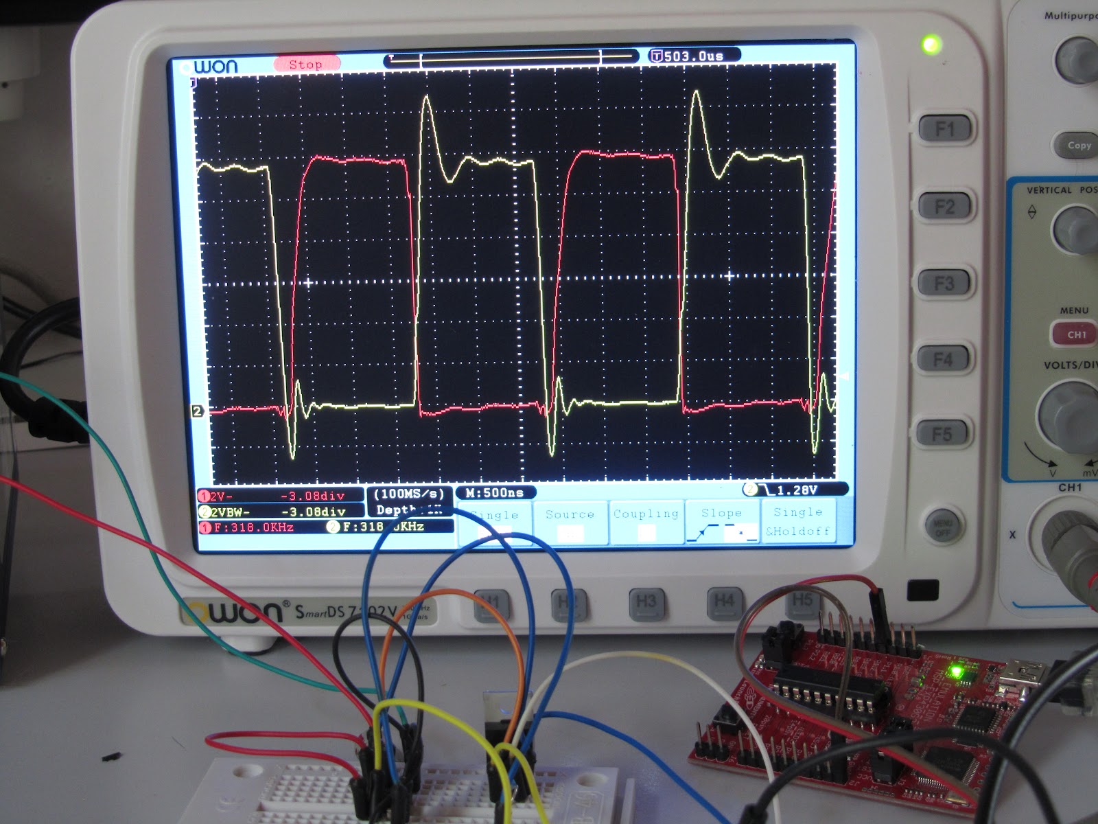
Channel 1 of the scope measures Vds (voltage between Drain and Source) which goes to (almost) zero when the gate is fully open.
Technically it's the voltage across the internal Rds resistor, so if it goes nicely down to zero it means we successfully drive the gate.
I will need to repeat this test with a higher load on the line (but not on the breadboard, melted plastic does not smell really nice).


Channel 1 is red and the volt scale is 2V per division.
You can see the zero level being marked by the little (1) red marker on the left side.
Channel 2 is yellow, showing the gate driver output, the two signals are inverted since when the gate signal (yellow) is high, it closes the circuit, so the Vds (red) drops to zero.
That's what I get at 80Khz.
I increased the frequency at about 320KHz and the result is visible in the picture below.


Both channels are now at 2V per division, aligned to their zero V.
You can see the rising edge of the Vds (red) being a bit "slow", that's definitely something that needs to be improved, which I assume can be achieved by discharging quicker the mosfet's gate.
Indeed proper cabling/pcb design is also needed, in fact the TC4420 can output up to 6A, no way that's going to happen using those tiny jumper wires.
I don't think it's something I can work on on a solderless breadboard like that, I probably need a better layout and definitely shorter connections.
Next step will be to add some caps, an inductive load on the output and  a freewheeling diode, that's where the real "magic smoke" could happen :)

Update : adding a 10Ohm gate resistor on the mosfet the signal becomes like this :


Normally a fast diode should be placed in parallel with the resistor, to improve the shutdown of the gate (or at least this is what I understood reading this interesting document)

Wednesday, August 29, 2012

DYI PCB

Today I made my first homemade Printed Circuit Board (PCB).

In the past I was lucky enough I could get access to some lab to produce them for me and today, does it still make sense to etch your PCB at home?

You probably get a much better result by using one of the many available online services that can produce professional grade PCBs for a reasonable price.... but that might eventually work if you know what you are doing... which, sadly, it's not my case.

By that I mean that any circuit I design and then test on a breadboard, has good chances it will not work once transferred on a PCB.
Why?
The answer is really simple : lack of experience which you can build up with the most classical process called "trial and error".

Now, if for every try and probable error I need to wait weeks for the pcb to be delivered to me I would consider that sub-optimal, it would not provide me a really steep learning curve.

I remember some years ago I saw a great BC comic strip :
BC (or was it Thor?) is pushing a square stone with a hole in the middle and says something like : "I had a wonderful Idea! This thing is called wheel and it will change the world as we know it".
In the next panel he comes back with  a triangular stone and goes : "I made a great improvement to my invention" and the other guy : "Uh? Where's the improvement?".
The answer is "I eliminated one of the four bumps".

So, to set the stage, I am pretty much there now : bumps optimization.
Not much, I agree, but it's always a good start to know were you stand.

I usually build circuit prototypes with breadboards, but it 's becoming more and more cumbersone since most of the components are now available in SMD packages.
I know there are adapters, but in the end I figured it's easier to be able to etch a quick PCB and use it instead... would have been fun anyway, so I thought.


Before I dig in further more : it actually worked, better than I expected (maybe my expectations were pretty low).
The board in the picture is 4 x 2.5 cm, pretty small... those pads on the bottom are for smd 805 components.
This should give you an idea of the size of the traces.

This one is just a test, my very first test, so I am pretty sure every step, from design onwards can be improved and yes, I could have started with something "simpler", maybe with bigger traces etc, but the purpose of this one was really to see where's the limit.

I still need to apply solder mask, so the process is not over yet.

How this was achieved :

I designed the pcb using Eagle Cad.
Nice tool, I chose this one mainly because you can type commands instead of clicking icons, I know it might sound silly to you, but it helps me a lot since my eyes make it difficult for me to use icons.
I created my own library with the two packages I needed, in that way I was able to design the pads with the shape I thought best to ease the soldering afterwards.
Soldering those tiny chips (and mainly the LDO on the right) will be difficult, hopefully I will have a good solder mask soon, without that I would not even try.
I designed the pads a bit longer than the suggested measure, I probably should have done more than that.
The idea is that it should be used to drag the solder away after applying it.
I suppose I will need to use the solder wick to remove shorts between the pins, but that's still to be discovered (wow, isn't that fun? So many things to try out!)
  
The circuit itself is really simple, it's a RS485 driver with a 3.3V LDO voltage regulator, nothing fancy, it should replace the one I am using on a breadboard.
It is also a part of a bigger circuit I am designing to host a MSP430G2553 (TSSOP). 


Once the PCB design was done I "panelized" 6 circuits (they are tiny, makes sense to run a batch of 6 at least) and printed some tests on plain paper, checking also that the solder mask overlapped nicely to the pads once printed.
Another check I did was to place the two chips on the paper and verify the contacts were sitting nicely on the pads (I designed the footprints in Eagle, had to test it).

To transfer the design to the copper I found two options you are probably familiar with :
- Photo resit and UV  light
- Toner Transfer

I have the equipment for the UV thing, a built myself a nice bromograph (I am quite proud of it :) Simple but apparently reliable), with 4 8W UVA lamps with ballasts and nice reflecting white inside. 
Yeah, told you I was proud of it, no? :)
But finally opted for the toner transfer as I found in the web people very happy with the results.
I will still use the bromograph for the solder mask.


The panel is laser printed (mirrored) on the toner transfer sheet (I had A5 sheets, managed to cut one in half for this test, to reduce the wasted material).
After cleaning the copper surface (dish soap first to remove finger prints etc, then a metallic wool sponge -gently- and water) I placed the pcb on a tempered glass (you can get them really cheap at Ikea, just look for shelves) with a bit of bi-adhesive.


Using a glass there helps a lot, it's a smooth solid surface, thermally suitable for this job and helps a lot also in aligning the toner transfer sheet with the board, I left on purpose some black borders around, to easily overlap the two parts.
Once the board was placed on the glass, I cleaned it with isopropilic alcohol.


You cannot see it properly in the picture, because of the flash, but placing the glass against a light source it is possible to use the black border to center the sheet and than secure it with some tape.


I initially overlapped a piece of fabric as I feared the yellow paper might stick to the iron, then I realized it is made specifically to be ironed... so it does not stick, nor it burns.
Thanks to the tape and the bi-adhesive the paper did not move even if I feared it might once it was really hot.
I then realized I might have overheated it, especially in the center.
Since everything is stuck to the glass, it's quite easy to handle, I used some cold water to cool down everything before peeling off the toner transfer sheet... which proved to be quite an easy task.


As you can see, in the center there is still a bit of toner, it probably happened because I overheated that area or because of the bi-adhesive tape on the back which absorbed part of the pressure I applied.
Checking the copper side revealed further signs of overheat, the copper appeared "reddish", darker than in the other area and  the toner was not covering completely the copper in some points.


I initially thought that the two boards in the middle would have been useless, but turns out I was wrong.


 I then etched using the classic FeCl solution, if you never used it, that thing is really messy, better use protection gloves and to keep it away from any metallic thing you are not planning to corrode.
To speed up the process, while gently rocking the container with one hand (while not holding he camera), I heated the solution with a hot air gun.
Combined with the fact that I tried to optimize the design to reduce the amount of copper that needed to be removed, the process was quite fast, probably around 5 minutes.


 The board is then rinsed with a lot of cold water.
A this point you can remove the remaining toner, but, if you are not planning to go ahead with the next steps, it's probably better to leave it there at it somehow protects the copper from further oxidation.


In my case I need to first check the result and then proceed with the solder mask part.
Since I am not sure at all of the outcome of the solder mask process, I decided to split the board in two to have two chances to run through the process, I then cleaned one.


I used a regular cutter, which did the job... but was probably not the best solution.
Using an aluminium guide to ensure the cut was traight helped a lot, specially since it was secured with two clamps.
These things make the job safer and easier, they come in extremely handy and can be easily found in hardware stores.


cleaning the toner away revealed that even the middle board, which I thought was useless due to the overheating, was pretty good.
In fact the first picture on top is the middle board, probably the worse in the batch.
Ok, I know, it could have been better, but you should realize those traces are really tiny, I could not find any short or broken trace after inspecting the pcbs with a magnifier.
The worse point is the one shown in the circle below.
It's the overheated part of the middle board, not perfect, but not too bad either in the end.
Check the pad on the right (red rectangle), it's 0.4 by 0.9 millimeters, that should give you an idea of the sizes in the picture.


Overall, for being my first attempt I am quite satisfied with the result, now I need to work out the solder mask part and then... the hand soldering.


Thursday, August 23, 2012

MSP430G2 - Pull up / down resistors

When using GPIO lines as inputs, you normally need to use pullup or pulldown resistors.
Most of the modern mcus now have them built in, selectable via software.

To understand why you need them I propose a simple and funny experiment with the MSP430 Launchpad.

Let's setup an extremely simple application, something that flashes the leds if we press the S2 button on the lanchpad.

The key thing here is that we are using a gpio input (p1.3) to detect whether the s2 button is pressed or not.
The flashing leds will just provide feedback on the fact that, yes, the button was pressed.

In order to show why we need pull resistors we will not configure one at the beginning

/*
 * main.c
 */

#include <msp430g2553.h>

void clockConfig()
{
 BCSCTL1 = CALBC1_16MHZ; // Set DCO
 DCOCTL = CALDCO_16MHZ;
 BCSCTL2= DIVS_2 + DIVM_0; // divider=4 for SMCLK and 1 for MCLK
}

void pinConfig()
{
  P1DIR |= BIT0  + BIT6; // leds = output
  P1DIR &= ~BIT3; // s2 = input
  P1OUT &= ~BIT0; // turn leds off
  P1OUT &= ~BIT6;
}

void main(void)
{
 WDTCTL = WDTPW + WDTHOLD;
 clockConfig();
 pinConfig();
 while (1)
 {
if ((P1IN & BIT3)>0) // if button bit is high
{ // flash leds
  P1OUT |= BIT0;
   P1OUT &= ~BIT6;
__delay_cycles(10000000);
  P1OUT &= ~BIT0;
   P1OUT |= BIT6;
         __delay_cycles(10000000);
}
 }


This experiment could eventually lead to unpredictable results (no worries, nothing will blow up -but hey, if it does don't call it on me! :P -), but hopefully we will be able to demonstrate the issue.

Now, the "magic" part :

Compile, load and run this simple software, let it run for a few seconds and watch the leds.
Nothing interesting happening there, right?
Ok, now without pressing it, touch with a finger the side of the button S2, you should survive this action.... unless a tiny and extremely poisonous scorpion was hiding behind it.

What happens?
The first thing is that you did not die, which is already a success for the experiment, but the most important thing is that eventually (depending on electrical charges on your body) you might have been able to trigger the state of pin p1.3.

While it looks pretty cool, we normally don't want that.
An input line left alone that way would eventually capture electrical charges from the surrounding environment, acting like an antenna.
The potential of such antenna would then be "floating" and it's difference to ground can be enough sometimes to reach a "1" logic state.

If we permanently connect a resistor (could be something like a 10K ohm) to ground we force -with a tiny current- the potential to level with the ground.
The amount of current needed to ensure this is in general very small, unless you have some extreme cases like you are designing circuitry for a nuclear weapon and such... but that's ok, I actually had to declare I will not use Code Composer Studio to create mass destruction weapons already.

Note : Isn't it funny' there is a country in the World were apparently you can buy an assault rifle with few question asked, but it gets tricky to download a C compiler just in case you could use it to produce weapons, which, admittedly, is the main usage of a C compiler :) 
Peace and love, stop using your compilers to kill people around the world (and smartly declaring it in online export forms at the same time)! 
Ah, I will ask you to sign some kind of declaration where you promise no to use my idea of hiding tiny scorpions behind push buttons.

Back to our resistors, the MSP430G2 enables them with the register P1REN, so let's just add the line

P1REN |= BIT3; 

in the pinconfig procedure.
Re-build, reload, ad re-execute and try again to touch the side of the button.
Yeah, I know, it was much more fun before, right?
 

Sunday, August 12, 2012

C2000 Piccolo - blinking an LED

Ok, this is my first program with the C2000 Launchpad, so I would start with something really basic, the MCU "Hello World" : Blinking an LED.

First of all, let's add the basic things we will probably always need :
We need the basic header file, we probably need to set the clock (clk + pll), stop the watchdog and access the gpio to blink the LED.

I recon we could start with something like this :


#include "DSP28x_Project.h"     // DSP28x Headerfile

#include "f2802x_common/include/clk.h"
#include "f2802x_common/include/gpio.h"
#include "f2802x_common/include/pll.h"
#include "f2802x_common/include/wdog.h"


void main()
{

 WDOG_Handle myWDog;
 myWDog = WDOG_init((void *)WDOG_BASE_ADDR, sizeof(WDOG_Obj)); 
 WDOG_disable(myWDog);
}

I know, this does not do much, right?
Let's see how we can add some more interesting stuff

  CLK_Handle myClk;
  PLL_Handle myPll;
  myClk = CLK_init((void *)CLK_BASE_ADDR, sizeof(CLK_Obj));
  myPll = PLL_init((void *)PLL_BASE_ADDR, sizeof(PLL_Obj));


 //Select the internal oscillator 1 as the clock source
   CLK_setOscSrc(myClk, CLK_OscSrc_Internal);

The clocking user guide states that there are two internal oscillators, both working with a base frequency of 10MHz, there are obviously also external options which we will not consider for this experiment.
To select the second internal oscillator we should use "CLK_Osc2Src_Internal"
Based on the oscillator frequency (10MHz if internal) the PLL (each internal oscillator has a pll) can be configured to set a multiplier and divider.

 PLL_setup(myPll, PLL_Multiplier_12, PLL_DivideSelect_ClkIn_by_2);
// the demo program states : 
// Setup the PLL for x10 /2 which will yield 50Mhz = 10Mhz * 10 / 2
// it looks more a 10MHz * 12 / 2 = 60 to me, which is the max speed of this device (and the multiplier_12 is the maximum value found in the enum declared in the header file)

the multiplier has a value from 1 to 12 and the divider can be 1,2,4.

The blue leds installed on the board (C2000 launchpad) are connected to gpio 0,1,2 and 3.
We will just use gpio_0, so let's configure it as output gpio pin.

 GPIO_Handle myGpio;

 myGpio = GPIO_init((void *)GPIO_BASE_ADDR, sizeof(GPIO_Obj));

 GPIO_setMode(myGpio, GPIO_Number_0, GPIO_0_Mode_GeneralPurpose);
 GPIO_setDirection(myGpio, GPIO_Number_0, GPIO_Direction_Output);

Actually, I found out that to turn the onboard LEDs we need to drive the signal low, and to turn them off the signal must be high.
For this reason, by default, all 4 leds are on (or at least this happened to me), so I specifically switched all them off before the loop for the blink.


    GPIO_setMode(myGpio, GPIO_Number_0, GPIO_0_Mode_GeneralPurpose);
  GPIO_setDirection(myGpio, GPIO_Number_0, GPIO_Direction_Output);
  GPIO_setMode(myGpio, GPIO_Number_1, GPIO_1_Mode_GeneralPurpose);
  GPIO_setDirection(myGpio, GPIO_Number_1, GPIO_Direction_Output);
  GPIO_setMode(myGpio, GPIO_Number_2, GPIO_2_Mode_GeneralPurpose);
  GPIO_setDirection(myGpio, GPIO_Number_2, GPIO_Direction_Output);
  GPIO_setMode(myGpio, GPIO_Number_3, GPIO_3_Mode_GeneralPurpose);
  GPIO_setDirection(myGpio, GPIO_Number_3, GPIO_Direction_Output);

  GPIO_setHigh(myGpio, GPIO_Number_0);
  GPIO_setHigh(myGpio, GPIO_Number_1);
  GPIO_setHigh(myGpio, GPIO_Number_2);
  GPIO_setHigh(myGpio, GPIO_Number_3);


Now, let's add a loop that turns the led on and off and le'ts cross our fingers :)

while(1)
{      
  GPIO_setLow(myGpio, GPIO_Number_0);
  DELAY_US(1000000);
  GPIO_setHgh(myGpio, GPIO_Number_0);
  DELAY_US(1000000);
}

Build, debug...
Does it work?
Not as expected for me, but I found out why.
What happened is that the delay was completely skipped.
By control-clicking it I found that function is actually defined in the DSP2802x_Examples.h file.
Something came back to my mind, while reading about the C2000 workshop I read something about memory segments and stuff that must be placed in the correct place... and I told to myself : "do I really need to care about that thing?".
Turns out that, yes, I have to.
To be honest, I didn't really get how the thing works yet (still reading), but the solution is to copy the functions from one area to another (or whatever is accomplished with the following lines).


#ifdef _FLASH
    memcpy(&RamfuncsRunStart, &RamfuncsLoadStart, (size_t)&RamfuncsLoadSize);
#endif

That, does the trick, but really, I will not attempt to explain it right now, I need to better understand it before.
Finally, this is my led blink source code :


/*
 * main.c
 */

#include "DSP28x_Project.h"     // DSP28x Headerfile

#include "f2802x_common/include/clk.h"
#include "f2802x_common/include/gpio.h"
#include "f2802x_common/include/pll.h"
#include "f2802x_common/include/wdog.h"


#ifdef _FLASH
    memcpy(&RamfuncsRunStart, &RamfuncsLoadStart, (size_t)&RamfuncsLoadSize);
#endif


void main()
{
 WDOG_Handle myWDog;
 myWDog = WDOG_init((void *)WDOG_BASE_ADDR, sizeof(WDOG_Obj));
 WDOG_disable(myWDog);

 CLK_Handle myClk;
 PLL_Handle myPll;
 myClk = CLK_init((void *)CLK_BASE_ADDR, sizeof(CLK_Obj));
 myPll = PLL_init((void *)PLL_BASE_ADDR, sizeof(PLL_Obj));

  CLK_setOscSrc(myClk, CLK_OscSrc_Internal);

  PLL_setup(myPll, PLL_Multiplier_12, PLL_DivideSelect_ClkIn_by_2);

  GPIO_Handle myGpio;
  myGpio = GPIO_init((void *)GPIO_BASE_ADDR, sizeof(GPIO_Obj));

  GPIO_setMode(myGpio, GPIO_Number_0, GPIO_0_Mode_GeneralPurpose);
  GPIO_setDirection(myGpio, GPIO_Number_0, GPIO_Direction_Output);
  GPIO_setMode(myGpio, GPIO_Number_1, GPIO_1_Mode_GeneralPurpose);
  GPIO_setDirection(myGpio, GPIO_Number_1, GPIO_Direction_Output);
  GPIO_setMode(myGpio, GPIO_Number_2, GPIO_2_Mode_GeneralPurpose);
  GPIO_setDirection(myGpio, GPIO_Number_2, GPIO_Direction_Output);
  GPIO_setMode(myGpio, GPIO_Number_3, GPIO_3_Mode_GeneralPurpose);
  GPIO_setDirection(myGpio, GPIO_Number_3, GPIO_Direction_Output);

  GPIO_setHigh(myGpio, GPIO_Number_0);
  GPIO_setHigh(myGpio, GPIO_Number_1);
  GPIO_setHigh(myGpio, GPIO_Number_2);
  GPIO_setHigh(myGpio, GPIO_Number_3);

  while(1)
  {
    GPIO_setLow(myGpio, GPIO_Number_0);
    DELAY_US(1000000);
    GPIO_setHigh(myGpio, GPIO_Number_0);
    DELAY_US(1000000);
  }

}

... and it blinks.

I also found a few issues with the linker not finding whatever it needed, I temporarily solved by cloning the demo project, removing the source and adding my new source.
Yup, I still have plenty of things to learn, that's he beauty of it, right?

[update : thanks to Trey@TI I found out what needs to be specified in the project properties when creating a new project from scratch (reporting it here just in case you encounter the same issue) :

1) in project -> properties -> CCS Build -> C2000 Compiler -> Include Options -> add dir : "C:\ti\controlSUITE\development_kits\C2000_LaunchPad"
2) in project -> properties -> CCS Build -> C2000 Linker -> File Search Path -> Include library : "C:\ti\controlSUITE\development_kits\C2000_LaunchPad\f2802x_common\lib\driverlib.lib"


]