If you don't, then, good for you, as you are probably really young or lived far away from technology!
Does it matter when dealing with VGAs?
Yest it does, as that standard was created to work with CRT monitors and even if we are not using them anymore, we still need to to follow crt related rules when we want to use it.
If you want to know more about Cathode Ray Tubes, you can check this interesting article from CERN.
Ok, so, VGA is an analog system that uses 3 color components (R,G,B) that are provided with 3 different signals that ranges from 0 to 0.7V.
0.7V means maximum intensity for every single color component and by varying the voltages of the three lines you can generate virtually all the RGB additive colors.
Easy enough, right?
There are other two signals, used to generate a vertical (VS) and an horizontal sync (HS).
If you know (or checked the linked article) how a CRT works, you also know that an electric and a magnetic fields are used to deflect horizontally and vertically the electrons emitted by the hot cathode, in their path to the screen (anode).
In CRT televisions and analog monitors, this deflection is programmed to be a scan from top to bottom and from left to right.
Those HS and VS signals tell the monitor at which speed they should perform such scan.
I.e. in the standard 640x480 VGA resolution , VS is 60Hz and HS is 31.5KHz (actually 31.4685KHz according to the specs).
This means that the CRT will be ready to retrace a new frame 60 times per second and within each frame it will be restarting a new horizontal line 31.500 times per second.
If you do the math, you will discover that this allows us to theoretically have 31.500 / 60 = 525 lines per frame.
We said before the resolution is supposed to be 480 lines, which is slightly less than the 525 we found.
That's why I said theoretically.
What happens is that the old CRT technology needed some time to adjust the magnetic and electric fields so that a new line and/or a new frame could be started.
This would not be the case with the current technology, still the VGA standard assumes that your R,G and B signals are silent (0V) at the beginning and at the end of a Horizontal or Vertical scan period.
Practically it means that you will need to generate a sync for 525 lines and ensure that (525-480)/2 at the border (called front porch and back porch) are kept completely black.
Same thing for the vertical border, the internal circuitry of a VGA monitor will likely assume you have about 800 columns, 640 of which are usable.
Technically you should calculate the borders as times, not rows and columns, but in a mcu or fpga implementation it just becomes easier to calculate them as rows and columns since you are calculating those anyways.
Actual numbers may vary, particularly when using multisync monitors, you may need to adjust this "grace period" describing the border around your usable area according to your monitor.
Technical specifications (source wikipedia) for the horizontal timing are the following :
| Parameter | Value | Unit |
|---|---|---|
| Pixel clock frequency | 25.175 | MHz[10] |
| Horizontal frequency | 31.469 | kHz |
| Horizontal pixels | 640 | |
| Horizontal sync polarity | Negative | |
| Total time for each line | 31.778 | µs |
| Front porch (A) | 0.636 | µs |
| Sync pulse length (B) | 3.813 | µs |
| Back porch (C) | 1.907 | µs |
| Active video (D) | 25.422 | µs |

and for the vertical Timing
| Parameter | Value | Unit |
|---|---|---|
| Vertical lines | 480 | |
| Vertical sync polarity | Negative | |
| Vertical frequency | 59.94 | Hz |
| Total time for each frame | 16.683 | ms |
| Front porch (A) | 0.318 | ms |
| Sync pulse length (B) | 0.064 | ms |
| Back porch (C) | 1.048 | ms |
| Active video (D) | 15.253 | ms |
All in all the HW interface is quite simple as you can see in the picture below (from www.fpga4fun.com) .
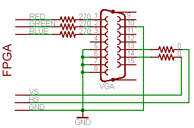
The 270Ohm resitors are used to generate a voltage divider with the internal impedance of 75Ohm which, supplied with a 3.3V voltage, would give us roughly the needed 0.7V.
Ok, all this is cool, but how does it fit in the FPGA design?
Of course this would work nicely with an MCU or an FPGA, but I think the FPGA solution is more appropriate in this case since you can dedicate some internal circuitry to handle the synchronization signals and have it work in parallel with your solution.
One way to go is to design a vga_synch module that generates the HS and VS signals, plus calculates the current X & Y coordinates.
Then we will have another module to use such coordinates in order to calculate R,G and B based on a mathematical formula, conditions or reading values from RAM (like it happens in a PC VGA card).
Implementation of the sync module
For practical reasons (this is also the case in real world applications), one single clock will be used for both the HS and VS signals, so VS will have a period which is an integer multiple of the HS period.
Also, we will use the same base clock to calculate the width of those signals and every single pixel.
Instead of creating my own module I will present the one provided with my FPGA board, so credits goes to some unknown author.
I will however deeply comment every single part of it, comments are mine, therefore all the shame deriving from possible mistakes goes to me :)
Before discussing the module itself, I have to specify that the clk signal is obtained by multiplying by two (in a pll) the board 50MHz clock, so it is a 100MHz clock fed to the sync module.
I don't know why they decided for this frequency since they are then dividing it by 4 in the Verilog module and nowhere the 100MHz frequency seems to be used.
They could have just divided by two the 50MHz and skip the pll.. but maybe this module was used also for higher resolutions.
module sync_module
(
CLK, RSTn,
VSYNC_Sig, HSYNC_Sig, Ready_Sig,
Column_Addr_Sig, Row_Addr_Sig
);
input CLK;
input RSTn;
output VSYNC_Sig;
output HSYNC_Sig;
output Ready_Sig;
output [10:0]Column_Addr_Sig;
output [10:0]Row_Addr_Sig;
All this just defines an input clock (the 100MHz we discussed before) and reset, plus the 5 outputs being HS,VS, the X counter, the Y counter and a flag (Ready_Sig) which accounts for the front/back porch times.
parameter T40NS = 3'd3;
reg [2:0]Count1;
always @ ( posedge CLK or negedge RSTn )
if( !RSTn )
Count1 <= 3'd0;
else if( Count1 == T40NS )
Count1 <= 3'd0;
else
Count1 <= Count1 + 1'b1;
This part is just used to implement the needed division by 4.
The variable Count1 is used and when it equals 3 (3'd3) it means 4 clock cycles passed (0 to 3), in other words a time lapse of 40ns (1/25MHz).
Conditions are : At reset restart from zero, at max count (T40NS) restart from zero, else just increment.
reg [10:0]Count_H;
always @ ( posedge CLK or negedge RSTn )
if( !RSTn )
Count_H <= 11'd0;
else if( Count_H == 11'd800 )
Count_H <= 11'd0;
else if( Count1 == T40NS )
Count_H <= Count_H + 1'b1;
Now we calculate the X counter (at each clock)
The counter itself is defined as a 11bit number reg [10:0]Count_H; (which also makes us think this module might have been used for higher resolutions, since for the 640 one 10 bits would have been enough).
At reset, as usual, start all over from zero, if we reached column 800 -see, we calculate front porch and back porch as columns instead of times, it's easier this way!- then back to column zero else IF we are at the 25MHz marker (Count1 maxed) increase the X counter.
reg [10:0]Count_V;
always @ ( posedge CLK or negedge RSTn )
if( !RSTn )
Count_V <= 11'd0;
else if( Count_V == 11'd525 )
Count_V <= 11'd0;
else if( Count_H == 11'd800 )
Count_V <= Count_V + 1'b1;
The Y counter mechanism is similar, with the only difference that it is reset to 0 when it reaches 525 and it is incremented when the X counter is maxed.
reg isReady;
always @ ( posedge CLK or negedge RSTn )
if( !RSTn )
isReady <= 1'b0;
else if( ( Count_H >= 11'd144
&& Count_H < 11'd784 )
&& ( Count_V >= 11'd35
&& Count_V < 11'd515 ) )
isReady <= 1'b1;
else
isReady <= 1'b0;
Now the isReady flag is calculated, it tells us if we are in the usable XY area or if we are in those black borders in which our R,G and B signals should be kept silent.
isReady is set true when X is between 144 and 784 (if you subtract them you obtain 640) and Y is between 35 and 515 (guess what you get if you subtract them? :) )
assign VSYNC_Sig = ( Count_V <= 11'd2 ) ? 1'b0 : 1'b1;
assign HSYNC_Sig = ( Count_H <= 11'd96 ) ? 1'b0 : 1'b1;
assign Ready_Sig = isReady;
assign Column_Addr_Sig = isReady ? Count_H - 11'd144 : 11'd0;
assign Row_Addr_Sig = isReady ? Count_V - 11'd35 : 11'd0;
Finally VS and HS are calculated based on the X and Y counters, their duration is respectively 3 rows and 97 columns (you can convert these in times if you like).
Also note these signals are negative.
Finally the real coordinates are computed (if we are in the usable area, identified by isReady = true) by subtracting the left and top border.
Will close it here today, going to explain the control module in the next post, but that's the easy part.
The 270Ohm resitors are used to generate a voltage divider with the internal impedance of 75Ohm which, supplied with a 3.3V voltage, would give us roughly the needed 0.7V.
Ok, all this is cool, but how does it fit in the FPGA design?
Of course this would work nicely with an MCU or an FPGA, but I think the FPGA solution is more appropriate in this case since you can dedicate some internal circuitry to handle the synchronization signals and have it work in parallel with your solution.
One way to go is to design a vga_synch module that generates the HS and VS signals, plus calculates the current X & Y coordinates.
Then we will have another module to use such coordinates in order to calculate R,G and B based on a mathematical formula, conditions or reading values from RAM (like it happens in a PC VGA card).
Implementation of the sync module
Also, we will use the same base clock to calculate the width of those signals and every single pixel.
Instead of creating my own module I will present the one provided with my FPGA board, so credits goes to some unknown author.
I will however deeply comment every single part of it, comments are mine, therefore all the shame deriving from possible mistakes goes to me :)
Before discussing the module itself, I have to specify that the clk signal is obtained by multiplying by two (in a pll) the board 50MHz clock, so it is a 100MHz clock fed to the sync module.
I don't know why they decided for this frequency since they are then dividing it by 4 in the Verilog module and nowhere the 100MHz frequency seems to be used.
They could have just divided by two the 50MHz and skip the pll.. but maybe this module was used also for higher resolutions.
module sync_module
(
CLK, RSTn,
VSYNC_Sig, HSYNC_Sig, Ready_Sig,
Column_Addr_Sig, Row_Addr_Sig
);
input CLK;
input RSTn;
output VSYNC_Sig;
output HSYNC_Sig;
output Ready_Sig;
output [10:0]Column_Addr_Sig;
output [10:0]Row_Addr_Sig;
All this just defines an input clock (the 100MHz we discussed before) and reset, plus the 5 outputs being HS,VS, the X counter, the Y counter and a flag (Ready_Sig) which accounts for the front/back porch times.
parameter T40NS = 3'd3;
reg [2:0]Count1;
always @ ( posedge CLK or negedge RSTn )
if( !RSTn )
Count1 <= 3'd0;
else if( Count1 == T40NS )
Count1 <= 3'd0;
else
Count1 <= Count1 + 1'b1;
This part is just used to implement the needed division by 4.
The variable Count1 is used and when it equals 3 (3'd3) it means 4 clock cycles passed (0 to 3), in other words a time lapse of 40ns (1/25MHz).
Conditions are : At reset restart from zero, at max count (T40NS) restart from zero, else just increment.
reg [10:0]Count_H;
always @ ( posedge CLK or negedge RSTn )
if( !RSTn )
Count_H <= 11'd0;
else if( Count_H == 11'd800 )
Count_H <= 11'd0;
else if( Count1 == T40NS )
Count_H <= Count_H + 1'b1;
Now we calculate the X counter (at each clock)
The counter itself is defined as a 11bit number reg [10:0]Count_H; (which also makes us think this module might have been used for higher resolutions, since for the 640 one 10 bits would have been enough).
At reset, as usual, start all over from zero, if we reached column 800 -see, we calculate front porch and back porch as columns instead of times, it's easier this way!- then back to column zero else IF we are at the 25MHz marker (Count1 maxed) increase the X counter.
reg [10:0]Count_V;
always @ ( posedge CLK or negedge RSTn )
if( !RSTn )
Count_V <= 11'd0;
else if( Count_V == 11'd525 )
Count_V <= 11'd0;
else if( Count_H == 11'd800 )
Count_V <= Count_V + 1'b1;
The Y counter mechanism is similar, with the only difference that it is reset to 0 when it reaches 525 and it is incremented when the X counter is maxed.
reg isReady;
always @ ( posedge CLK or negedge RSTn )
if( !RSTn )
isReady <= 1'b0;
else if( ( Count_H >= 11'd144
&& Count_H < 11'd784 )
&& ( Count_V >= 11'd35
&& Count_V < 11'd515 ) )
isReady <= 1'b1;
else
isReady <= 1'b0;
Now the isReady flag is calculated, it tells us if we are in the usable XY area or if we are in those black borders in which our R,G and B signals should be kept silent.
isReady is set true when X is between 144 and 784 (if you subtract them you obtain 640) and Y is between 35 and 515 (guess what you get if you subtract them? :) )
assign VSYNC_Sig = ( Count_V <= 11'd2 ) ? 1'b0 : 1'b1;
assign HSYNC_Sig = ( Count_H <= 11'd96 ) ? 1'b0 : 1'b1;
assign Ready_Sig = isReady;
assign Column_Addr_Sig = isReady ? Count_H - 11'd144 : 11'd0;
assign Row_Addr_Sig = isReady ? Count_V - 11'd35 : 11'd0;
Finally VS and HS are calculated based on the X and Y counters, their duration is respectively 3 rows and 97 columns (you can convert these in times if you like).
Also note these signals are negative.
Finally the real coordinates are computed (if we are in the usable area, identified by isReady = true) by subtracting the left and top border.
Will close it here today, going to explain the control module in the next post, but that's the easy part.
No comments:
Post a Comment